
Expendable Foam Pattern
A temporary pattern defines the casting shape.
CASTING PROCESS GUIDE
Understand how an expendable foam pattern, refractory coating, dry sand, pouring, shakeout and sand reclamation work together — and what each stage needs to control.
01 / DEFINITION
Lost foam casting uses an expendable foam pattern to represent the final casting geometry. The pattern is assembled, covered with a refractory coating and placed in unbonded dry sand. During pouring, molten metal replaces the pattern as the foam decomposes or evaporates. The resulting process connects pattern quality, coating condition, sand support, gas management, pouring and post-pour recovery in one route.
A temporary pattern defines the casting shape.
Unbonded dry sand supports the coated pattern.
Molten metal replaces the pattern as it decomposes.
02 / MATERIALS
Foam pattern material, refractory coating, dry sand and casting metal each affect how the process should be planned. Final selections remain project-specific.
Pattern material is selected around the required geometry, pattern process, handling route and project requirements. Confirm the material and pattern-making route before defining equipment or process controls.
The coating supports surface control, permeability and gas management around the foam pattern. Coverage, consistency and compatibility with the surrounding process should be reviewed together.
Unbonded dry sand needs a suitable flow and support behavior for filling, vibration, mold stability and later recovery. Reuse and reclamation are part of the wider sand cycle.
The casting metal is selected by the part, metallurgy, design and required process conditions. Metal suitability and process details should be confirmed for the specific project rather than assumed from a generic list.
WHY THE INTERFACES MATTER
The pattern material decides how cleanly the foam is replaced, the coating how the surface and gas path behave at that interface, the dry sand whether the mold stays supported around the geometry, and the metal which pouring and cooling conditions apply.
03 / PROCESS ROUTE
The route is shown as a process guide. Actual equipment selection and interfaces are confirmed around the casting and project requirements.
Foam beads or pattern material are prepared and formed into the required shape. The pattern becomes the temporary form around which the later mold is built.
The pattern establishes the geometry that the metal will reproduce. Pattern quality, handling and dimensional consistency should be reviewed before the pattern enters the next stage.
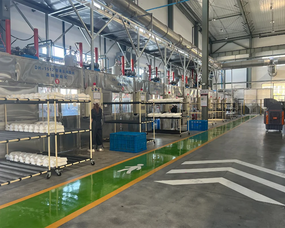
Individual foam elements are assembled into a pattern cluster or casting assembly. The assembly route is selected around the casting geometry, handling method and subsequent coating operation.
Assembly quality affects how the pattern is coated, positioned and supported in the sand. Interfaces, joints and handling points should be clear before the assembly is transferred.
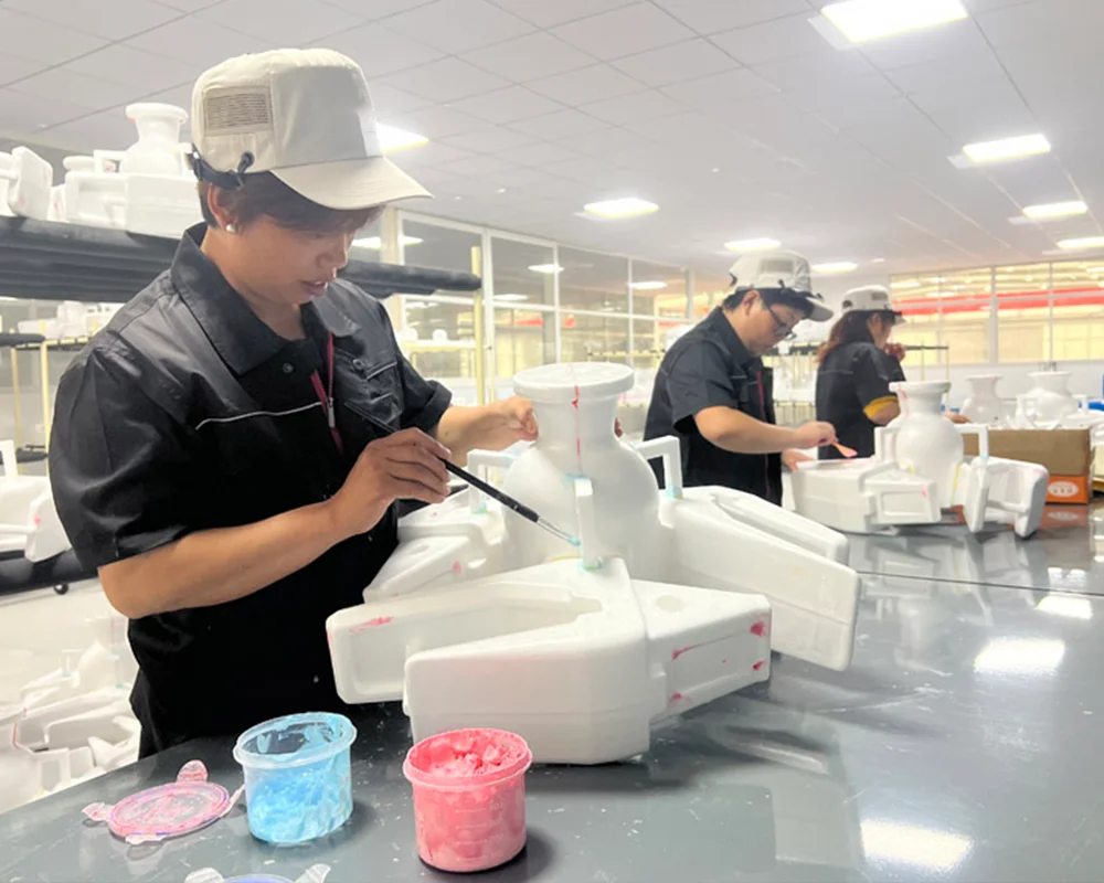
The assembled foam pattern receives a refractory coating selected for the pattern, metal and sand process. Coverage, consistency and handling are reviewed before the coated pattern enters drying.
The coating forms an important interface between the decomposing pattern, molten metal and surrounding sand. Its condition can influence surface result, permeability and the way gases leave the mold.
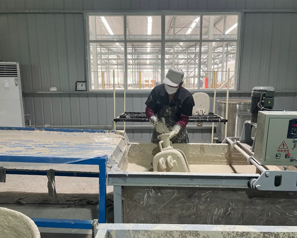
The coated pattern is moved through a drying step suited to the coating and pattern requirements. Air movement, handling and the condition of the coating are considered together.
A pattern that is not ready for sand filling can affect coating integrity, gas behavior and handling stability. Drying is therefore a process checkpoint rather than only a waiting step.
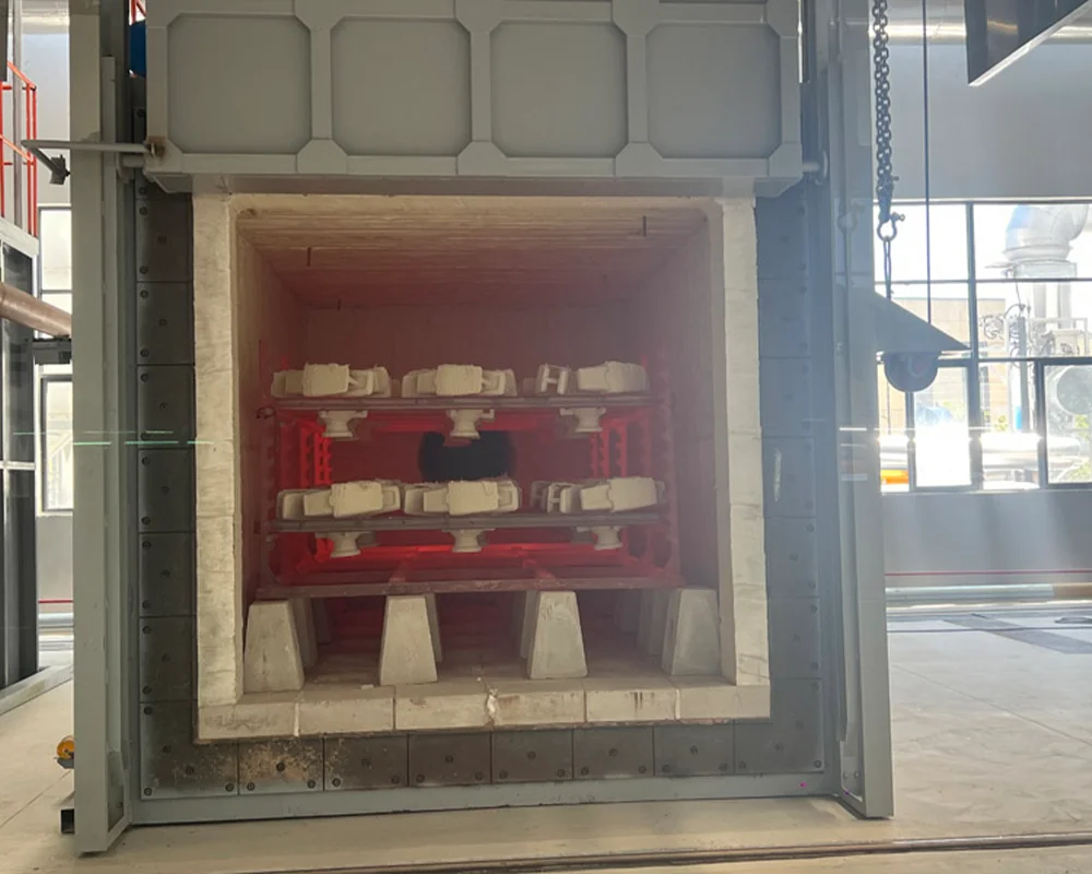
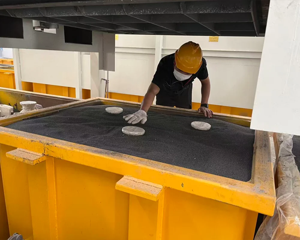
The coated pattern assembly is positioned in the flask. Dry sand is introduced around the pattern and vibration is used to help the sand flow into available spaces and support the assembly.
Sand flowability, fill uniformity and compaction affect pattern support during pouring. The route should avoid damaging the pattern while maintaining a stable mold around complex geometry.
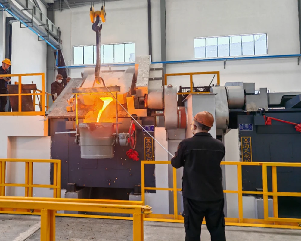
Molten metal enters the prepared mold while the foam pattern decomposes or evaporates. The mold is then held or moved through a cooling stage selected for the process route and casting requirements.
Pouring is the point where the pattern, coating, sand and metal conditions interact. Vacuum, pouring sequence, transfer and cooling interfaces should be considered as one process stage.
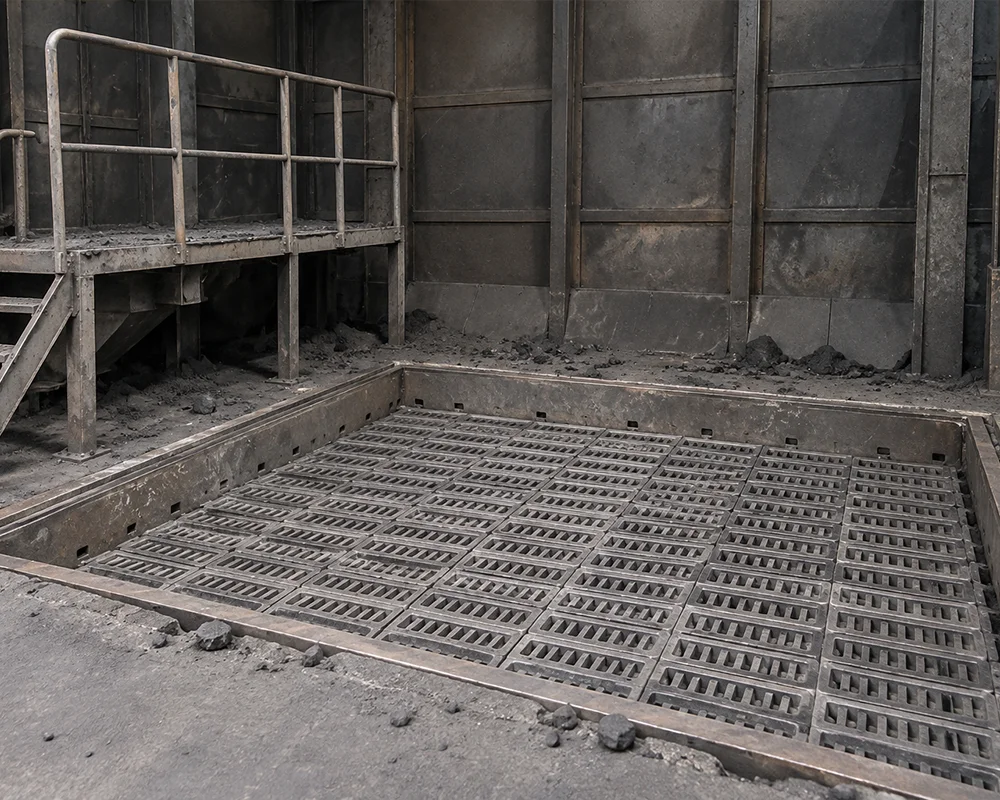
After the required cooling stage, the flask enters shakeout, where the casting, flask components and used sand are separated and moved to their respective downstream routes. The used sand then passes through screening, cooling and reclamation before it returns to the sand-filling cycle.
Shakeout influences casting handling and the condition of the material entering recovery, while reclamation connects the end of one mold cycle to the next. Separation route, sand condition, dust control, storage and return movement belong to the same discussion.
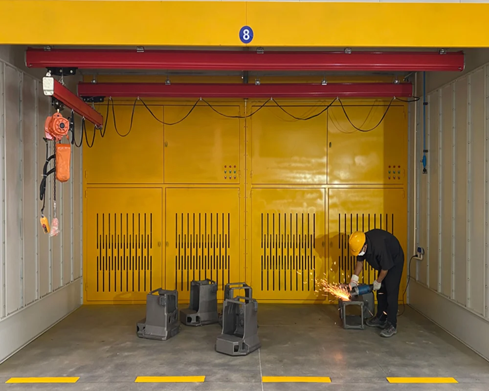
The separated casting moves through the finishing activities defined for the part and project. Excess material, surface residue and inspection handoffs are handled according to the agreed process scope.
Finishing closes the process route and makes the handoff to inspection, machining or shipment clear. The required activities depend on casting design and downstream requirements.
04 / SAND CYCLE
Dry sand is not consumed with the casting: it supports the mold during pouring and then returns to the process route. Reclamation connects the end of one mold cycle to the next sand-filling cycle, so sand condition, dust control, storage and return movement belong to the same discussion.
Used sand is screened, reclaimed and conditioned before it is introduced around the next coated pattern.
Where a vacuum arrangement is used, it is handled together with the pouring route, gas path and equipment configuration. Whether it applies to a given project is confirmed during the process review.
05 / INVESTIGATION FRAME
The factors below are possible contributors, not absolute diagnoses. Review the related stage, available evidence and process conditions before deciding on a correction. A deeper defect and remedy review belongs to the process discussion rather than this overview.
| Problem | Possible Contributing Factors | Related Stage |
|---|---|---|
| Porosity | Possible contributing factors may include gas path, coating condition, sand condition or pouring interaction. | Coating / Drying / Pouring |
| Carbon-related Defects | Possible contributing factors may include pattern decomposition, coating behavior, gas management or metal interaction. | Pattern / Coating / Pouring |
| Incomplete Filling | Possible contributing factors may include pouring sequence, pattern arrangement, thermal behavior or mold conditions. | Pattern Assembly / Pouring |
| Mold Collapse | Possible contributing factors may include sand support, fill uniformity, vibration practice or flask handling. | Sand Filling & Compaction |
| Dimensional Variation | Possible contributing factors may include pattern repeatability, assembly, support, cooling or downstream handling. | Pattern / Sand / Cooling |
| Surface Defects | Possible contributing factors may include coating coverage, sand condition, gas behavior or finishing route. | Coating / Sand / Finishing |
06 / EQUIPMENT
Eight machines from the line, in process order from bead foaming to sand cooling. Each tile links back to the stage it serves, where the controls and interfaces are written out in full. The wall shows selected equipment, not a complete line scope or quoted specification.
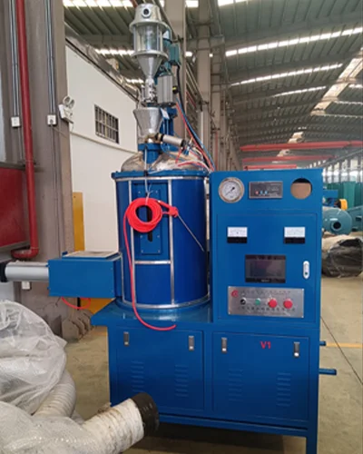 Foaming MachineFoam pattern making
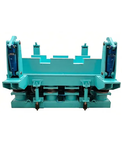 Clamping Vibration TableSand filling & compaction
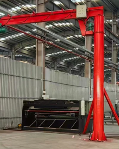 Single-Beam CranePouring & cooling
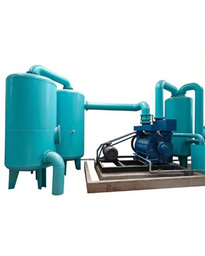 Vacuum SystemPouring & cooling
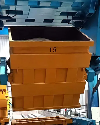 Flask InverterShakeout & sand recovery
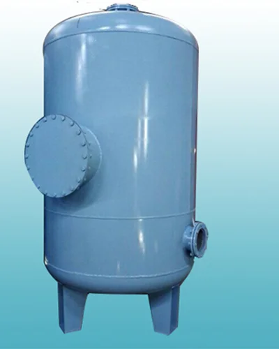 Filter TankShakeout & sand recovery
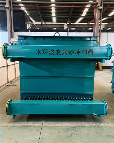 Water-Ring Sand CoolerShakeout & sand recovery
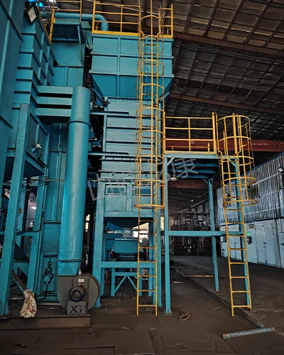 Sand Processing CoolerShakeout & sand recovery
07 / APPLICATION FIT
Two blocks only: the characteristics that make this route worth reviewing, then the same dimensions set against the processes a part like yours is usually weighed against. Both are a starting point for the technical review, not a suitability guarantee.
The expendable pattern defines the casting shape directly, so features that would otherwise need separate cores can be formed by the pattern itself.
Because the pattern is not withdrawn from a bonded mold, parting design can often be simplified. The final arrangement still follows the pattern and mold design review.
The mold is unbonded dry sand introduced and vibrated around the coated pattern, so the molding route carries no binder preparation or curing stage.
Hollow sections and internal channels can be represented by the pattern assembly rather than assembled cores inside the mold.
Used sand is screened, cooled and reclaimed, then introduced around the next coated pattern instead of leaving the route after one casting.
Pattern, coating, sand, pouring and recovery are reviewed together, so a change at one stage is read against the stages around it.
LOST FOAM VS OTHER PROCESSES
| Dimension | Lost Foam Casting | Green Sand Casting | Investment Casting |
|---|---|---|---|
| Pattern | Expendable foam pattern | Reusable pattern route | Wax pattern and shell route |
| Mold material | Unbonded dry sand around coated pattern | Green sand mold | Ceramic shell |
| Parting line | Can be reduced depending on pattern and mold design | Parting design is part of the mold route | Parting and shell handling depend on the pattern and shell design |
| Complexity | Useful for complex geometry subject to project review | Depends on mold, core and parting requirements | Useful for detailed geometry subject to shell and handling review |
| Tooling route | Pattern-making tooling and assembly route | Pattern, core and molding route | Wax tooling, shell building and dewaxing route |
| Process characteristics | Pattern replacement during pouring and sand reclamation context | Bonded or green sand molding route | Shell-based precision casting route |
08 / QUESTIONS
These are the questions that come up first when a part is being weighed against this route. If yours is not here, send the drawing or specification and it is answered against the actual project.
The route is reviewed against geometry first: cast-in features, internal passages and shapes that would need several cores in a bonded mold are where it is usually considered. Suitability still depends on the drawing, the material, the size range and the production objective, so a part is confirmed through a technical review rather than from a category list.
The pattern is an expendable foam made from a bead material selected around the geometry, the pattern process and the repeatability the part needs. Depending on batch size and geometry, the pattern route can be a molded pattern from tooling or a machined pattern, and that route is fixed together with the drawing before the rest of the process is defined.
Send the tooling details with the drawing and they are checked in the technical review. Whether existing tooling can be used depends on its condition, the pattern process it was built for and the geometry it has to produce, so it is answered per project. Ownership and storage of any tooling are agreed with you before production starts.
The refractory coating is selected for the pattern material, the casting metal and the surrounding sand, because it is the interface between the decomposing pattern, the molten metal and the mold. Coverage, permeability and the condition of the coating before sand filling are stage controls, which is why drying is treated as a checkpoint rather than a waiting step.
No, vacuum is a process option rather than a fixed step. Where it is used it is planned together with the pouring route, the gas path, the sand support behavior and the equipment configuration, so whether it applies to your casting is confirmed during the process review.
They are set by the pattern route, the tooling, the flask and the pouring conditions rather than by one published figure, so they are reviewed against the drawing instead of being quoted in advance. Thin walls and long sections are the cases that need the most attention, because pattern handling, coating support and pouring behavior all meet there.
The sand is unbonded and is not consumed with the casting, so the route is closed by screening, cooling, dust collection and reclamation before the same sand is introduced around the next coated pattern. Sand condition, storage and return movement belong to the same discussion as filling and compaction.
The defect table on this page is an investigation frame, not a diagnosis: each entry points at the stages that can contribute to it. A review starts from the evidence at hand — pattern condition, coating and drying records, sand and pouring conditions — and works back to the stage that explains it before any correction is made.
START A PROJECT
Share the casting type, material, size or weight, target capacity, current process issue and equipment need. The first discussion can focus on process fit before any line or equipment scope is defined.