AUGER COMPONENT REFERENCES / SINGLE & MULTI-BLADE FORMS
Auger Bits& Parts
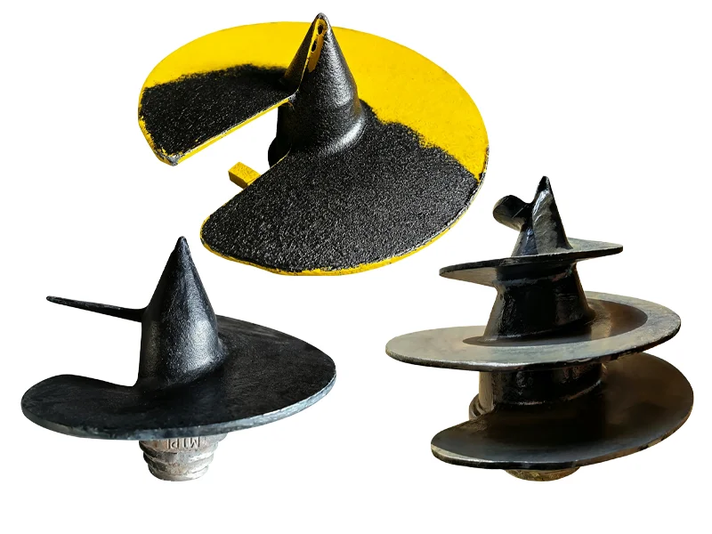
Compare the single-blade and multi-blade auger components listed in this category. Share the reference, connection dimensions and intended use for review.
Brand names identify catalog references and do not imply affiliation. Model references alone do not confirm compatibility. Numbered references distinguish source entries and do not establish different geometries.
A MODEL IS ONLY THE START
Can’t Find Your Part?
Send the details you have so the part can be identified and reviewed.
Use these stages to specify the process and inspection requirements for your part.
01
Casting
Part geometry & material
02
Heat Treatment
Hardness requirements
03
Machining
Mounting dimensions
04
Inspection
Acceptance criteria
05
Surface Finishing
Surface requirements
Material grade, hardness, dimensions and acceptance criteria are confirmed during technical review.
APPLICATION & SELECTION
Application Requirements
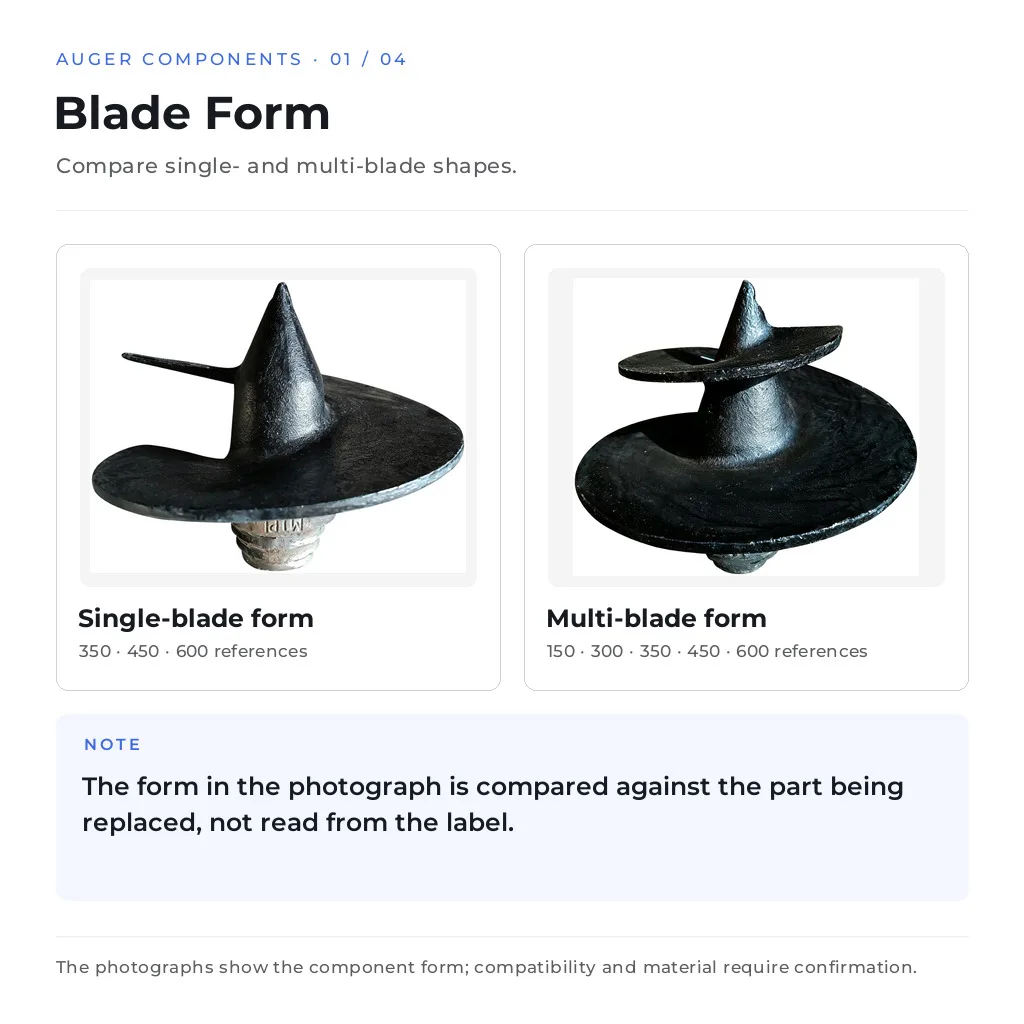
Blade Form
Compare single- and multi-blade shapes.
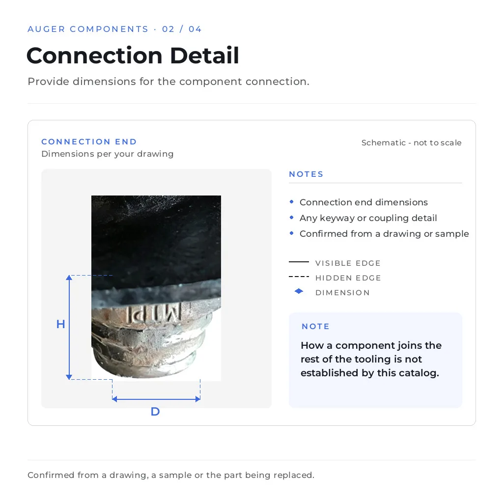
Connection Detail
Provide dimensions for the component connection.
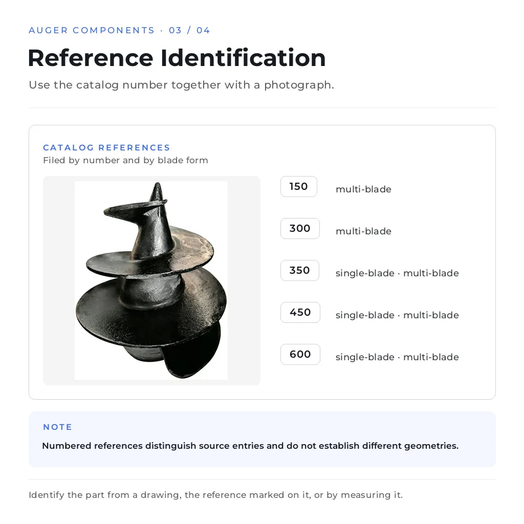
Reference Identification
Use the catalog number together with a photograph.
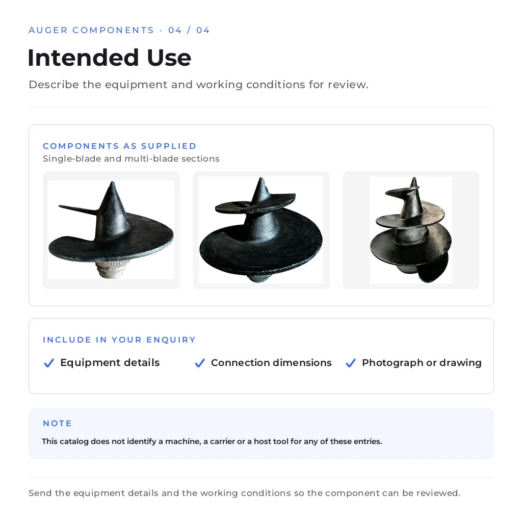
Intended Use
Describe the equipment and working conditions for review.
A CLEARER SOURCING CONVERSATION
Why Work With Us
From model selection to a clearly defined inquiry.
Reference-focused selection
Compare the listed part references and component forms.
OEM project discussion
Bring drawings, samples and marking requirements.
Technical review
Define material, process and inspection requirements.
Bulk-order planning
Organize quantities by part for your purchasing inquiry.
FROM REFERENCE TO REQUIREMENT
How to Order
A typical order follows these steps, subject to the agreed quotation.
Send Reference / Part Number
Confirm Product / Drawing
Quotation
Production
Inspection
Shipment
BEFORE YOU INQUIRE
Frequently Asked Questions
What do 150, 300, 350, 450 and 600 represent?
They are the source reference labels each entry was collected under. No unit and no dimensional meaning is established for them by this catalog, so they are not read as a diameter, a length or a machine class, and they are not a universal part number. Identify the part from a drawing, from the reference marked on the component itself where it is still legible, or by measuring the part being replaced, and send the reference numbers together with those measurements so the two can be matched.
What is the difference between the single-blade and multi-blade groups?
They are the form labels carried by the source entries: one group is filed as single-blade and the other as multi-blade, and the same reference number can appear in both. That is why the label alone does not settle which part is needed. Compare the blade form in the photographs against the part being replaced and confirm the geometry from a drawing or a measurement, because the catalog states neither the blade count nor any section dimension for these entries.
Which machines or tooling do these components fit?
This catalog does not identify a machine, a carrier or a host tool for any of these entries, and no compatibility is implied by the reference numbers or by the group labels. Fit is confirmed from your information: the equipment details, the connection dimensions of the component and a photograph or drawing of the part being replaced. Where none of that is available, the connection end and the overall form are what make a component identifiable, so those are the first things to photograph.
How do I identify a component when nothing is legible on it?
Measure and photograph it: the number of blades and their form, the overall length, the blade width and thickness, and the connection end with its dimensions and any keyway or coupling detail. Photograph the part from the side and from the connection end with a tape measure in frame so the scale is readable. Those measurements are compared with the listed entries to propose the closest match, and where nothing matches they are enough to start a drawing-based replacement.
What material and manufacturing route do these components use?
The photographs and source names do not establish a material grade or a manufacturing route for any entry, so none is claimed here. Rotating auger tooling is produced in more than one way in the industry - flighting or blades welded onto a tube or shaft, and one-piece cast or forged sections are both used, with the connection often machined on a separate coupling - and this catalog does not say which applies to a given entry. For a specific part the material, the joining method and any heat treatment are agreed during technical review, and the agreed requirement is recorded so it can be checked on the delivered parts.
Can a component be produced to a drawing?
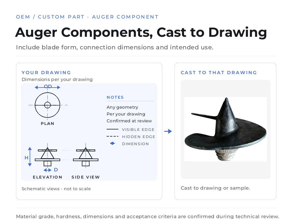
Yes. Send the drawing or a sample together with the blade form, the connection detail, the material and the quantity required, and the geometry, production route and inspection plan are confirmed during technical review. Any hardness or wear requirement is recorded so it can be verified on the delivered parts. Where there is no drawing, the measurements and photographs described above are enough to start the review, and the connection end is the detail that most often decides whether a replacement can be made.
LET’S IDENTIFY YOUR PART
Request a Quote
Send us your model, part number, drawing or product photo. We’ll help identify the correct part and prepare a quotation.
✓Machine model
✓Part number
✓Drawing
✓Product photo
✓Required quantity
Drawings and technical files are kept confidential

 OEM / CUSTOM PART · AUGER COMPONENT