DFM for Aluminum Castings: Hot Tearing, Shrinkage and Alloy Choice
An aluminum casting that cracked on the bench, leaked after machining, or refused to clean up on a flange is rarely a foundry mistake. In most cases the mold did exactly what the drawing asked for, and the drawing asked for a shape that aluminum cannot freeze soundly.
That is the argument behind DFM for aluminum castings. Rules that work on a gray iron housing do not transfer, because aluminum freezes over a wide interval, moves heat quickly and shrinks more. Copy them across and the failure appears after the pattern is cut, when a change is expensive.
What follows sticks to the three defects that scrap most aluminum castings, to the way alloy choice changes the design envelope, and to the split between what the drawing must state and what the foundry owns.
Why aluminum castings are not designed like iron castings
Four material behaviors explain nearly every aluminum-specific rule.
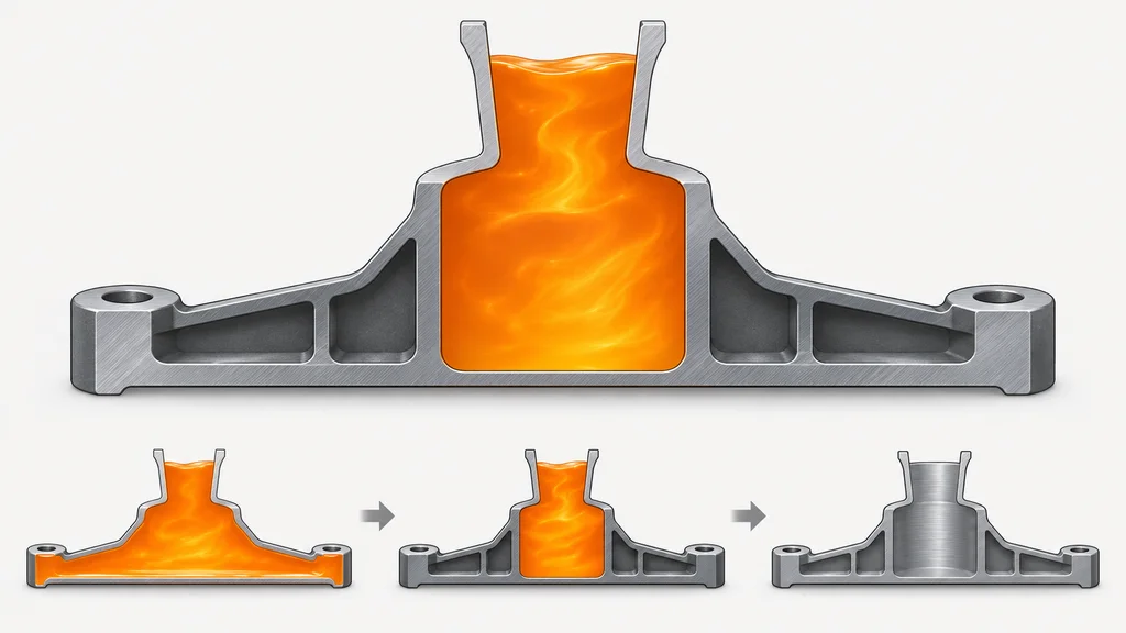
A wide freezing range. Most aluminum casting alloys pass through a long mushy stage where solid dendrites and liquid coexist. In that stage the metal cannot feed itself well and cannot carry load. Near-eutectic gray iron behaves differently: a sound skin advances inward and the part becomes rigid early. A shape that freezes as a shell in iron freezes as a sponge in aluminum.
High thermal conductivity. Aluminum pulls heat through itself, not only into the mold. A thin wall can be solid while the riser neck is still open, and a heavy boss can stay liquid long after the plate around it is rigid. Sections do not reach rigidity together, which is where shrinkage and strain both come from.
High solidification shrinkage and short feeding distance. The volume deficit must be fed from somewhere, and in aluminum the path closes early. Feeding works over a shorter distance than iron practice suggests.
A stubborn oxide film. Aluminum oxide forms instantly and does not weld back to itself. Every time the metal surface folds over in the mold, an oxide film is trapped inside the casting. It is invisible, it does not heal, and it becomes a leak path or a crack starter later.
The consequence is short: spend metal where it can be fed, and avoid shapes that build strain while the metal is weak.
Fact: DINGDAR runs four in-house casting routes (green sand, shell molding, lost foam and investment) at its 180,000 m² plant, with 720+ employees and 52 engineers and R&D staff. Route and alloy are reviewed against the geometry before tooling is cut.
Hot tearing: why long thin walls and sharp corners crack
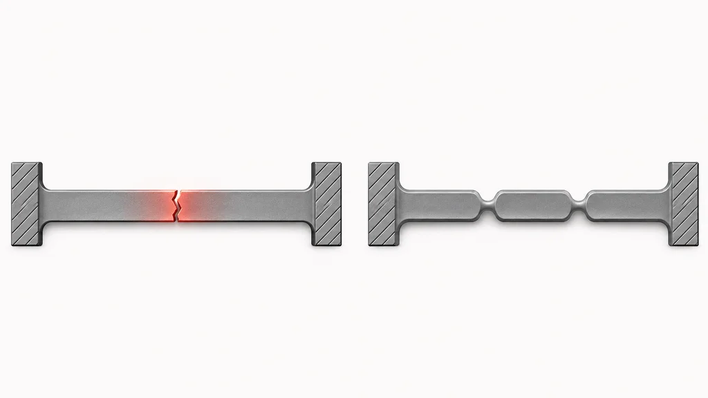
A hot tear is an intergranular crack that opens while the casting is still hot, at the end of freezing, when the alloy is a coherent skeleton of grains with thin liquid films between them. The casting is contracting; the mold, the cores and the colder sections around it are not, so strain concentrates in those films, they tear, and the tear is either fed by residual liquid or left open.
Three conditions must coincide: a weak range that lasts long enough, restraint on contraction, and a geometry that concentrates strain. Aluminum supplies the first by nature. Design usually has to remove the third.
Where hot tears start
Long straight walls are the classic case. Contraction is resolved along the length of the wall, and both ends are held by a flange, a boss or a corner that has already gone rigid, so it tears in the middle.
Sharp internal corners concentrate the same strain at a point, and they are also a hot spot, because two sections meet there and freeze last. A thin wall joined to a heavy boss fails where they meet: the wall is rigid first, the boss contracts afterwards, and the junction is the only place that can give. Closed frames are the worst version, because a rim fully restrained at four corners has no compliant path at all.
Four drawing-level levers
Radius the corner. An internal radius spreads strain over a length of wall instead of a point, and it removes the hot spot where two sections merge. A generous radius is cheaper than a riser.
Rib instead of mass. If a section needs stiffness, ribs deliver it with thin, fast-freezing metal rather than a thick wall that must be fed.
Segment the wall. Windows, slots or an offset break contraction into short lengths that can move. Where one casting cannot be made to work, split it in two and bolt them: a joint is often cheaper than a cracked casting and a rejected batch.
Pre-curve the wall. A slight bow, cambered away from the restrained side, gives contraction somewhere to go. It looks odd on a drawing and it works.
What the foundry changes
Grain refinement, a gating pattern that sets a favorable thermal gradient, mold and knockout timing, and a mold that yields rather than holding. Those belong to the foundry. But if the drawing has a straight, fully restrained wall, no process fix will make it reliable. Draft and wall basics are in wall thickness and draft DFM rules; the point here is the strain path.
Shrinkage porosity: finding the thermal node first
Shrinkage porosity is the void left when a region freezes without liquid to replace the volume it loses. In a wide-freezing-range alloy it appears as distributed micro-porosity on the grain boundaries; in a narrow-range alloy or a heavy section it appears as a concentrated cavity. Both forms obey one rule: the last region to freeze must draw liquid, and the riser must still be liquid when it does.
The node is a geometry fact
A thermal node is a region with more volume per unit of cooling surface than its surroundings, and it need not be an obviously heavy wall. Typical nodes are a boss root, the intersection of two or three ribs, a thick flange on a thin shell, the corner where three walls meet, and a section thickened to carry a thread.
At each of these the surrounding thin metal freezes first and closes the feed path, so the node freezes in isolation. You can find them on a drawing before any study, by comparing how much mass sits behind each unit of surface, junction by junction.
Wall transitions
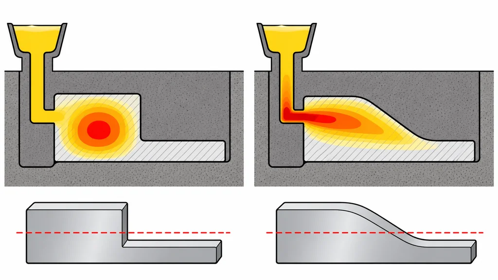
A step change in thickness is the most common avoidable node on a casting drawing. Two adjacent sections of very different thickness cannot freeze progressively, because the thin one is rigid before the thick one needs feeding.
Replace the step with a taper long enough that the transition freezes directionally toward the heavy end. The note on the drawing matters as much as the geometry: state a controlled taper rather than a chamfer, so the pattern shop does not shortcut it.
Feeding logic, in order
The sequence matters when a casting shows porosity:
- Reduce or redistribute the mass. Thinning a heavy section beats feeding it.
- Open a feed path, with a taper or a rib, so the node can draw from a region that is still liquid.
- Move the last-freezing point deliberately, with a chill or a change in the surrounding section, so it lands where a riser can reach.
- Size and place the riser, with a neck that stays open longer than the section it feeds.
Most shops jump straight to step four. Skip the first three and the riser becomes a heavy node of its own, so the porosity moves rather than disappears.
In permanent mold work the trade is easier, because the die removes heat from the part directly and risers can be smaller. Gravity casting is worth discussing whenever the part is a repeatable shape at moderate volume, since the die sometimes solves a feeding problem that sand cannot.
Gas porosity and entrained air: why a bigger gate backfires
Two different problems get called gas porosity.
Hydrogen
Aluminum melt dissolves hydrogen, and its solubility drops abruptly as the metal freezes, so gas comes out of solution in the last liquid and forms round pores. They sit where the metal froze last, often where shrinkage also appears. Melt treatment and degassing address it; design addresses it by keeping porosity-prone sections away from sealing faces and from surfaces that must be pressure tight.
Entrained air and oxide film
This one is created by the fill, and the drawing has a say in it. Every time the metal stream breaks surface, falls, or turns a sharp corner at speed, it folds oxide film into itself. In aluminum that film is strong and does not diffuse away, so the folded layer stays as an internal discontinuity. It reduces strength, and it gives hydrogen somewhere to collect.
The gating ratio argument
A gating system is a chain of restrictions: sprue, runner, gate. Flow rate is set by the smallest of them, and the pressure profile is set by how their areas relate. When a casting shows porosity and someone proposes a larger gate, the choke usually moves upstream into the runner, the runner stops running full, metal falls through it, and entrained air goes up. The gate is bigger and the fill is dirtier.
What helps is designing the system as a unit: a tapered sprue that stays full, a runner that stays full, a gate that enters where metal can spread without a jet, and often a filter. That is the foundry's decision, which is why a drawing should not dictate gating.
Venting is a geometry request
Air in the cavity has to leave before the metal arrives, through the sand, the parting line, vents or core prints, and geometry decides whether it can.
A deep blind pocket at the top of the mold traps air. A closed box needs a core, and that core needs a vent path out. A pocket sealed by the parting line on every side has nowhere to breathe, so give it a vent land or accept a drilled hole before the pattern is made.
The same logic explains why thin, long, complex shapes often run better in investment casting, where the shell is permeable, the mold is hot, and the fill is easier to control.
Alloy choice redraws the design envelope
Buyers often pick an alloy from a property table before the geometry is settled, then ask the foundry to hit the number. In aluminum, alloy and geometry are one decision.
Casting alloys and wrought alloys are not interchangeable
A356 and its relatives were designed to be cast: they are fluid, they tolerate the wide freezing interval, and they respond to heat treatment. 6061 was designed to be extruded and machined. Its properties are useful in wrought form and its castability is poor in cast form, because the composition that makes it strong and workable as a wrought product makes it hot short and sluggish as a liquid.
A part cut from 6061 plate therefore does not become the same part when it is cast. It becomes a casting-alloy part with different sections, possibly a heat treatment, and properties that have to be checked rather than assumed. If the design depends on wrought properties, casting may be the wrong process, and that is much cheaper to learn before the pattern.
Within the casting alloys, more silicon improves fluidity and reduces hot tearing tendency, which widens the geometry you can cast. Treat that as a tendency and verify it for the actual grade and lot (typical range, to be confirmed against actual inspection).
Heat treatment moves the part
A T6 cycle includes a rapid quench, and a rapid quench puts a long, thin, asymmetric casting into tension on one side and compression on the other. Two consequences land on the drawing.
Distortion. The part will not come out of treatment straight. Either the geometry is made symmetric enough to distort predictably, or stock is left on the faces that will be trued afterwards.
Blistering. Subsurface porosity that was tolerable as-cast can expand during solution treatment and raise a blister on a machined or cosmetic face. A node that would have been a radiograph finding becomes a visible reject, so porosity-prone regions should sit away from those faces.
Designing for the machining stage
Aluminum is soft and springy next to the irons it replaces. A thin wall clamped in a vise moves, and a bore machined in a deflected wall is round in the fixture and oval on the bench. Three habits reduce that: thicken the area around a clamping point, or add a boss that exists only to be clamped; choose a datum machined first that stays stable; and mark where the part may be supported.
At moderate volume the die route changes these constraints again, because the die controls cooling and reduces scatter: gravity casting is the usual conversation there.
What the drawing must say, and what the supplier owns
A drawing that states everything becomes unbuildable, and one that states nothing becomes a negotiation after the first reject. Split it by who controls the variable.
The buyer's lines
- Alloy and temper by standard designation, or a written equivalent-agreement clause.
- Which faces are as-cast and which are machined, face by face.
- The datum scheme, with datum targets on as-cast surfaces if that is what the fixture will use.
- Critical-to-function features, and how each will be verified.
- Pressure tightness, sealing requirement and test medium, where relevant.
- Surface treatment, and whether porosity is acceptable on a visible face.
- Inspection level, documentation, marking, first article, and any zone needing volumetric inspection, marked on the drawing rather than described in an email.
The foundry's lines
- Gating and riser design, and the filling pattern.
- Pattern or die layout, parting line and core strategy.
- Shrink compensation on the pattern or the die model.
- Draft, applied to the geometry as the process needs it.
- Pouring and melt treatment practice, knockout and heat treatment cycle, sampling location and the process window.
- Alloy certification and the actual test results.
Defect, cause and countermeasure
| Defect | What causes it | Design-side countermeasure | Foundry-side countermeasure |
|---|---|---|---|
| Hot tear | Strain at the end of freezing in a restrained thin section | Radius internal corners, rib instead of thicken, segment long walls, pre-curve | Grain refinement, fill and gradient control, later knockout |
| Shrinkage porosity | Isolated heavy section that freezes after its feed path closes | Even out section mass, taper transitions, move bosses to corners | Riser placed and sized to freeze last, chills, open feed path |
| Hydrogen porosity | Gas rejected from solution in the last liquid to freeze | Keep heavy sections away from sealing and cosmetic faces | Melt treatment and degassing, charge and tool control |
| Entrained air and oxide film | Turbulent fill, falling stream, runner not running full | Do not dictate gating from the drawing, flag long thin flow paths | Tapered sprue, full runner, filtered and bottom-fed entry |
| Blister after heat treatment | Subsurface porosity expanded by the quench | Move nodes away from machined faces, avoid thin-over-thick at a seal | Lower gas content, inspect before treatment |
| Distortion | Uneven section and quench stress | Symmetric sections, ribs for stiffness | Straightening fixture, stress relief, quench control |
Fact: DINGDAR holds ISO 9001, IATF 16949, ISO 14001 and ISO 45001 certification, and inspects in house for chemistry, dimensions, hardness, mechanical properties, microstructure and internal soundness. Alloy, heat treatment and inspection scope are fixed in one technical review before tooling.
Where this leaves the drawing
Aluminum gives a narrow window. It must be fed while it is mushy, free to contract while it is weak, and filled without folding its own oxide into itself. Every rule above comes from one of those three sentences, and none of them need exotic geometry, only a drawing read as a solidification problem rather than as a shape.
If a part is already in trouble, the useful starting point is not a new tolerance but a section map: where the mass is, where it freezes last, where it is restrained, and where it will be machined. The engineering team at DINGDAR reviews aluminum geometry against the route that will actually cast it. Start with about us for the plant and the four casting routes, then send the drawing or the sample through contact. Replies normally come back within 12 to 24 hours.
FAQ
What is the minimum wall thickness for an aluminum casting?
There is no universal number, and any page that gives you one without asking about the alloy, the process and the part size is guessing. The limit comes from how far the metal flows before it freezes and whether the section can be fed. Ask the foundry for its demonstrated capability on a comparable part, then confirm it on the first article.
Can an aluminum casting replace a cast iron part directly?
Rarely as a direct substitution. Aluminum has a lower elastic modulus, so a part chosen for stiffness deflects more at the same section, and the geometry needs ribs rather than scaling. Where iron was chosen for mass, conductivity or corrosion, aluminum wins, but the sections change with it.
Do I need mold flow simulation before releasing the drawing?
It depends on the part. For a thin, long, complex casting, or one with a heavy section that must be fed, a filling and solidification study answers two questions cheaply: where air will be trapped and where the last metal freezes, though it is only as good as the data behind it.
How thin can a thin-wall aluminum casting be?
Thin enough to be a problem, usually. A thin wall must fill before it freezes, be fed from somewhere, and survive handling, machining and service. The practical limit falls as part size grows, because flow length grows faster than the wall stays liquid. Success comes from a short flow path, a hot mold, a vented cavity and a foundry that has cast that wall before.
Why did my aluminum casting crack weeks after delivery, or during machining?
Two candidates. A hot tear may have formed at the end of freezing and stayed closed until machining opened it or handling loaded it. Or residual stress from an uneven section and a fast quench was sitting in the part, and the first cut redistributed it. Both trace back to geometry: a restrained thin section, or one that was never symmetric.
Should I specify A356 or 6061 for a casting?
They are not alternatives in the same category. A356 belongs to the casting alloy family: formulated to be poured, and responsive to heat treatment. 6061 is a wrought alloy for extrusion and machining, and a poor casting alloy. If the requirement is genuinely a wrought property, the honest answer may be to keep machining from plate.
Who decides the gating and riser design, the buyer or the foundry?
The foundry, and the drawing should leave room for it. Gating depends on pattern layout, molding line, alloy lot and pouring practice, none of which the buyer controls. Specify the outcome instead: which faces must be sound, which must be pressure tight, and what inspection proves it.
Sources
- ASM International, ASM Handbook Volume 15: Casting, reference material on solidification, feeding and defect formation. https://www.asminternational.org/
- American Foundry Society, technical resources on aluminum casting practice and defect analysis. https://www.afsinc.org/
- ISO 8062-3:2023, Geometrical product specifications (GPS), dimensional and geometrical tolerances for moulded parts, castings. https://www.iso.org/standard/77952.html