Wall Thickness and Draft: DFM Rules for Cast Part Geometry
A casting can look perfect in CAD and still cause trouble the moment it hits the shop floor. Of all the geometry decisions behind that, two drive more scrap, rework and tooling churn than almost any others: wall thickness and draft. Between them they decide whether liquid metal fills the cavity cleanly and whether the part leaves the mould intact.
Wall thickness and draft are easier to get right when you treat them as one coupled system. This guide gives recommended starting values by process and alloy, shows how the two rules interact, and covers how to specify both on a drawing. The aim is simple. For the engineers, buyers and project managers who sign off casting geometry, the DFM review should land before the pattern is cut, not after the first batch fails.
Why wall thickness and draft decide castability
Castability is the sum of two physical questions. Will the metal fill every cavity before it freezes, and will the solid part come out of the mould intact?
Wall thickness answers the first question. The cross-section sets how much heat the metal carries and how fast it solidifies. Thin sections freeze quickly and may never fill. Thick sections stay liquid longer and feed thinner neighbours, right up to the point where the thick section starves and shrinks.
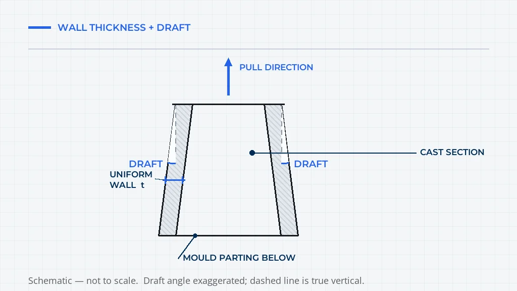
Draft answers the second. Every face parallel to the pull direction has to slide out of the mould, and draft is the slight taper that turns that slide into a clean release instead of a scrape.
Get both right and the rest of the DFM checklist falls into place. Get either wrong and no amount of finishing hides it. A wall that is too thick leaves porosity that shows up as a leak or a soft spot in service. A face with no draft leaves drag marks and sand inclusions. Both problems trace back to the model, where they are cheaper to fix than on the tool.
Wall thickness rules for castings
Minimum wall thickness by alloy
The minimum wall is the thinnest section the metal can fill reliably before it solidifies. It falls as fluidity rises and as the thermal mass of the mould drops. Aluminium fills thin sections more easily than steel, and a heated investment shell lets metal travel further than a cold sand mould.
Values below are typical starting points for sand-moulded castings. Use them to flag risky geometry, then confirm the exact floor with the foundry for your alloy, part size and section length.
| Alloy family | Typical minimum wall | Common working range | What drives the floor |
|---|---|---|---|
| Grey iron | About 3 mm | 4 to 12 mm | Good fluidity, but thin long sections lose heat fast |
| Ductile iron | About 4 mm | 5 to 15 mm | Needs feed metal to offset shrinkage |
| Cast steel | About 6 mm | 8 to 20 mm | High melting point and low fluidity |
| Stainless steel | About 5 mm | 6 to 15 mm | Similar to steel, plus higher cost of scrap |
| Aluminium | About 2.5 mm | 3 to 8 mm | Best fluidity of the common structural alloys |
| Copper alloys | About 3 mm | 4 to 10 mm | Comfortable fluidity, wide range by grade |
Minimum-wall ranges are compiled from industry and foundry design guidance ([1], [3], [4], [5], [6]). Confirm the exact floor with the foundry for your alloy.
Two cautions sit behind that table. First, the floor is not a target. A part that sits exactly at the minimum has no margin, so keep the working thickness above the floor wherever the section is long, curved or hard to feed. Second, minimum wall scales with part size. A 4 mm wall is generous on a small bracket and risky across a large housing, where the metal travels further and loses more heat.
Uniform wall thickness and transitions
Uniformity matters more than any single minimum. When every section cools at roughly the same rate, the casting avoids the locked-in stresses that cause distortion, hot tears and warping after shakeout.
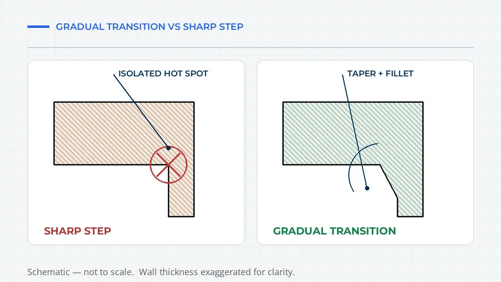
Keep wall thickness within about plus or minus 25 percent of the nominal wall across the part [7]. Where a genuine wall change is unavoidable, blend it. Instead of a step, use a gradual taper so one section feeds the next without a hard boundary. A transition that runs at a slope rather than a cliff lets the metal flow smoothly and lets heat leave evenly.
Thick sections need attention. Once a wall passes roughly twice the nominal thickness, the extra metal does not add strength in proportion to its weight. It adds a slow-cooling mass that pulls feed metal from thinner neighbours and leaves internal shrinkage. If the design needs stiffness, add ribs or a boss instead of thickening the wall.
Fact: DINGDAR, Henan Dingdar Machinery Equipment Manufacture Co., Ltd., has produced castings since 1986 and runs four in-house casting routes: green sand, shell moulding, lost foam and investment. Engineering support reviews wall thickness, transitions, fillets and draft before any pattern or die is cut.
Ribs, bosses and junctions
Ribs let a designer add stiffness without adding a heavy wall. The familiar rule is to keep rib thickness at roughly 50 to 60 percent of the adjoining wall [6]. A rib that is as thick as the wall it joins cools slower and pulls a sink mark across the visible surface, so the rib does its structural job and leaves a cosmetic defect.
Bosses follow the same logic. A boss on a thin wall should taper outward and blend with generous fillets so heat leaves gradually. Sharp junctions between ribs, bosses and walls act as hot spots, so fillet them. As a guide, internal fillet radius often runs at about the wall thickness, and external corners can be a little larger [8].
Keep ribs apart as well. Ribs spaced too closely create a thick mass between them, so the cooling benefit of thin ribs is lost. Spacing ribs at several times the rib thickness keeps the material between them close to the nominal wall.
Draft angle rules for castings
What draft actually does
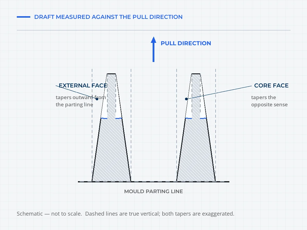
Draft is the taper applied to a face relative to the direction the pattern or part pulls. A face with zero draft lies flat against the mould along its full height. The moment the pattern starts to move, the whole face resists at once. The result is friction, drag and, in a sand mould, a cavity wall that crumbles.
Add a small angle and the face only touches near the parting line. As the pattern moves, the gap widens immediately and the rest of the face never contacts the mould. Ejection force drops, the surface survives, and the pattern lasts longer.
Recommended draft angles
The right draft depends on surface depth, finish, and whether the face is external or formed by a core. Deeper faces need more draft, because the total clearance grows with height and a shallow angle over a tall face still leaves contact near the top. Textured or abrasive surfaces also need more, because the mould grips them harder [9].
The table below gives typical starting values. Depth is the main variable, so treat the "recommended" column as a baseline and add draft as faces get deeper.
| Feature | Typical minimum | Recommended starting value |
|---|---|---|
| External vertical faces | 0.5 to 1 degree | 1.5 to 3 degrees |
| Internal faces and pockets | 1 to 1.5 degrees | 2 to 5 degrees |
| Cored holes and cores | 1 to 1.5 degrees | 2 to 3 degrees |
| Investment casting faces | 0.5 degree | 1 to 2 degrees |
| Deep pockets, per extra depth | Add about 1 degree per 25 mm | Scale with depth |
| Textured surfaces | Add on top of base draft | Add about 1.5 degrees per 0.25 mm of texture |
Draft ranges are typical starting values drawn from cross-process design guidance ([1], [2], [3], [9]). Confirm them against your process route and surface finish.
A useful field method: think in clearance, not degrees. On a shallow face, a small, consistent clearance per side is usually enough. On a deep face, check the clearance at the far end rather than trusting the angle alone, because that is where binding happens.
Fact: DINGDAR operates 180,000 m2 of production plant with 720+ employees and 52 engineers and R&D staff, and holds ISO 9001, IATF 16949, ISO 14001 and ISO 45001 certification. Casting the same geometry across four routes in one plant is what makes cross-process DFM advice practical rather than theoretical.
Internal and external draft, and cored features
External faces taper outward from the parting line, so the part gets narrower as it pulls away from the mould. Internal faces and cores taper the opposite way, widening toward the parting line, so the core can withdraw without dragging. Getting the sense wrong turns a well-drafted part into a negatively drafted one, which locks the mould shut.
Cored features need their own attention because they may pull in a different direction from the main body. A side core, a sliding core, or a hole that runs across the parting line all have independent pull directions, and each direction needs its own draft. That is why a draft analysis on the whole model can look clean while one core face hides a problem. Review cores separately and confirm the pull direction of each.
A zero-draft exception exists, but treat it as rare. A face that will be machined away after casting does not need draft on the cut surface, though the surrounding pattern still does. Flat parting-line faces also sit at zero draft by definition, because they separate rather than slide. Outside those cases, draft every face.
How wall thickness and draft interact
The two rules are not independent. Most of the subtle mistakes live in the interaction.
Thicker walls generally want more draft. A thin wall presents a small contact area and releases with a light taper, while a thick wall has more surface in contact and, in a permanent mould, shrinks onto the core harder as it cools. If a design thickens a section, revisit its draft rather than leaving the original angle in place.
Draft also changes the effective wall thickness. A drafted wall is not one thickness; it is a range that narrows or widens along the pull direction. On a tall drafted face, the thickness at the bottom can differ noticeably from the thickness at the top. When the designer checks wall thickness, they should expect that variation and make sure the thinnest point along the draft still clears the minimum.
The interaction runs the other way too. A face too thin to draft heavily, because more draft would thin it further, needs a different process or orientation rather than a compromise. That decision belongs in a process review, which is why choosing the casting route early matters. The companion guide on how to choose a casting process for wear parts walks through that choice in more detail.
| Situation | Wall thickness response | Draft response |
|---|---|---|
| Thick structural section | Check for internal shrinkage, consider ribs instead | Increase draft to offset greater contact and shrink |
| Long thin section | Raise above minimum floor to keep fill | Add draft to avoid drag on a long face |
| Deep pocket | Keep walls uniform, avoid local thickening | Add draft that scales with depth |
| Cored hole | Verify the thinnest wall along the core | Draft each core to its own pull direction |
| Textured surface | Unchanged base wall | Add drafting for texture on top of base value |
Putting wall thickness and draft on the drawing
DFM rules only help if they reach the pattern shop and the moulder. That means the model, the drawing and the general notes all have to agree.
Model wall thickness as real, measurable geometry, and add the nominal wall value to the drawing so the reviewer can check uniformity at a glance. Call out thin or critical sections explicitly, since those are the areas most likely to shift when tolerances stack up.
For draft, state the pull direction and the parting line the draft relates to. A draft angle without a pull direction is ambiguous, and an ambiguous note is how negative draft sneaks into a pattern. Add a general note for default draft on unnamed faces so nobody has to guess, and flag any face that must stay vertical.
Keep draft out of the dimensional tolerance stack unless the drawing says otherwise, since draft is a fabrication angle rather than a controlled dimension in most cases. Where a specific draft value is functional, for example on a sealing face, call it out separately and tell the foundry it is critical.
The way these notes are captured at quoting stage matters. The guide on how to compare casting quotations shows how to check that a quote reflects the actual geometry, and not a simplified version of it.
Common wall thickness and draft mistakes
A short checklist catches most problems before they become expensive:
- Setting a wall at the exact minimum with no margin for long or curved sections.
- Mixing thick and thin walls with sharp steps instead of gradual transitions.
- Thickening a whole wall when a rib would add stiffness more cheaply.
- Leaving a face at zero draft because it reads as vertical in the model.
- Drafting the main body but forgetting side cores and cross-parting features.
- Assuming one draft angle fits every face regardless of depth or finish.
- Treating draft as part of the tolerance stack when it is a fabrication angle.
- Signing off geometry before a wall thickness and draft analysis has been run.
Each is a modelling decision, cheap to fix in the model and costly to fix in tooling. An early review with the foundry closes the gap between engineering intent and the pattern shop. The guide on how to evaluate a casting supplier covers what to look for in that review.
For higher-volume parts, the process route changes the rules. A shell-moulded or green sand casting part tolerates different minimums and draft than an investment-cast part of the same shape, and each route's moulding equipment sets its own practical limits. Buyers who understand those limits write clearer drawings and get fewer surprises. You can review the published design and DFM material, or start a project through custom castings when the geometry is non-standard.
Fact: DINGDAR's inspection covers six areas on the shop floor: chemical composition by direct-reading spectrometer, dimensions by CMM, hardness by Brinell tester, mechanical properties by universal testing machine, microstructure by metallographic microscope and internal defects by ultrasonic flaw detector.
FAQ
What is the minimum wall thickness for a casting?
There is no single number, because the minimum depends on the alloy and the process. As a practical starting point, aluminium can run thinner than ferrous alloys, and investment casting holds thinner sections than green sand. Most foundries work from a floor of about 2.5 to 3 mm for light alloys and 4 to 6 mm for iron and steel in sand moulds, then adjust for part size, section length and how the metal fills the cavity. Treat any published value as a starting estimate rather than a guarantee, and confirm it against the specific alloy and moulding route before the geometry reaches the pattern shop.
What is a typical draft angle for castings?
Most castings carry 1 to 3 degrees of draft on external walls and 2 to 5 degrees on internal walls and pockets. The exact figure moves with surface depth, finish, and whether the wall is formed by the mould or by a core. Sand castings often sit at the higher end because the mould is rigid and rough, while investment and shell castings can use less. The rule of thumb is to draft every vertical face, add more for deep pockets and textured surfaces, and never leave a face at zero draft just because it looks vertical in the model.
Why do castings need a draft angle?
Draft lets the pattern or the part leave the mould without tearing the surface. A vertical wall has full contact with the sand or the die along its whole height, so removing it drags metal and sand against each other. A small taper breaks that contact early and lets the part release cleanly with less force. Draft also protects the mould: without it, the pattern scrapes the cavity on every cycle, which shortens tool life and adds drag marks, scuffs and edge damage that show up in the finished casting and in the inspection record.
How does wall thickness cause casting defects?
Wall thickness drives how fast each section cools, and uneven cooling is behind most wall-related defects. A wall that is too thin can freeze before the metal fills it, giving cold shuts and misruns. A wall that is much thicker than its neighbours cools last, so it pulls metal from the thinner sections and leaves shrinkage porosity, sink marks or hot tears. Uniform walls with gradual transitions between thick and thin areas keep cooling even, which is why the uniformity rule matters more than any single minimum.
Does draft angle increase part cost?
Draft costs almost nothing in material, but the geometry decisions around it change tooling and yield. Good draft reduces ejection force and drag, so tools last longer and fewer castings need rework. The cost appears when draft is missing and the foundry has to compensate with extra hand finishing, slower cycles, higher scrap rates, or a pattern rebuilt with draft added later. Because pattern changes mean re-cutting tooling, the cheapest draft is the draft added during the first DFM review, before the pattern or die is made.
What happens if a casting is designed with zero draft?
A zero-draft face sticks. In a sand mould the pattern drags the cavity wall on every draw, so the sand crumbles and the casting picks up rough patches, sand inclusions and broken edges. In a permanent mould it can seize, gall, or need so much ejection force that the part distorts or cracks. Foundries can sometimes machine draft into the pattern as a workaround, but that changes the part, adds a step to the quote, and does not always recover the intended dimensions. Design draft in from the start and the problem never reaches the shop floor.
Sources
- Steel Founders' Society of America (SFSA). "Steel Castings Handbook, Supplement 2." 2017. https://www.sfsa.org/wp-content/uploads/2021/10/s2.pdf - Steel minimum wall thickness and the definition of draft.
- Dynacast. "A Beginner's Guide to Die Cast Design." 2026. https://www.dynacast.com/en-sg/resources/article/a-beginners-guide-to-die-cast-design - Draft ranges by metal.
- metal-castings.com. "Sand Casting Design Guidelines." 2026. https://metal-castings.com/sand-casting-design-guidelines-draft-angles-wall-thickness-tolerances/ - Sand draft ranges and wall minimums.
- MULAN Casting. "Minimum wall thickness for sand casting." 2025. https://www.mulanmetal.com/what-is-the-minimum-wall-thickness-for-sand-casting/ - Wall minimum by alloy.
- LB Foundry. "Sand Casting Tolerances & Wall Thickness." https://www.lbfoundry.com/sand-casting-design.html - Wall thickness and machining allowance.
- Engineers Edge. "Design For Sand Casting." https://www.engineersedge.com/sand_cast.htm - Rib and wall thickness rules.
- jtrmachine.com. "How Wall Thickness and Draft Angles Affect Tooling Cost." 2026. https://www.jtrmachine.com/die-casting-design-guide - Wall variance of plus or minus 25 percent.
- Manufacturing Network. "Sand Casting: The Designers & Buyers Guide." https://www.manufacturingnetwork.com/knowledgebase/view/30 - Fillet radius of about 1 to 1.25 times wall thickness.
- Protolabs. "Draft Angle Guidelines for Injection Molding." 2026. https://www.protolabs.com/resources/design-tips/improving-part-moldability-with-draft/ - How draft changes with depth and texture.
- DINGDAR. Company information, 2026. https://hndingdar.com/about-us - Casting routes, certifications and inspection equipment.