Investment Casting Design Rules: Wall Thickness, Gating and Wax Pattern Limits
Investment casting design rules are usually published as a table of numbers, which is the least useful form they can take. The constraints that matter come from four places: how thick the metal must be to fill and then feed, what the wax pattern and die can produce, where the gating can feed from, and whether the internal geometry can be cored and cleaned out. Get those four right and the part is ordinary. Get one wrong and every later stage inherits it.
This guide covers the lost wax route on its own terms, because its limits do not transfer from sand or lost foam. It is written for engineers and sourcing teams who have already decided the shape needs precision and now need to know where the process will push back. DINGDAR runs investment casting as one of four in-house routes, so the notes below describe constraints cleared on real first articles.
Why This Process Can Hold Shapes Other Routes Cannot
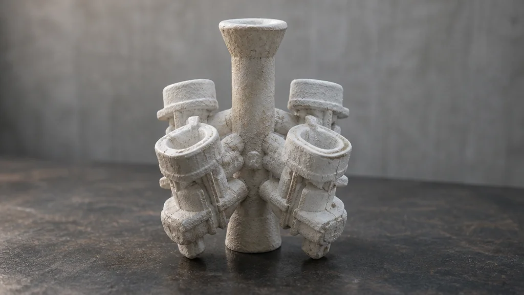
The pattern is wax, and it is destroyed on purpose. The shell is built by dipping the assembly in ceramic slurry and stuccoing it with refractory grain, layer after layer, until the coating can survive pouring. The wax is then melted out, leaving a monolithic ceramic cavity in the shape of the part. Metal fills it, and the shell is broken away afterwards.
Three consequences follow. There is no parting plane in the mould, for a start. A sand mould must be split so the pattern can be withdrawn, and that split leaves a parting line, flash and a draft requirement on every vertical face. A shell has no split, so a functional surface can run straight through where a parting line would otherwise sit.
Second, the mould is consumed to release the part, so nothing has to slide or be drawn. Undercuts, re-entrant angles and internal passages become geometric questions rather than impossibilities.
Third, the wax die works cold and at low pressure. It can be split into many small segments with slides and loose pieces wherever the shape demands, so complexity moves into the tool, paid once, instead of into the part, paid every cycle.
That is why buyers come here for internal passages that would otherwise be drilled and plugged, and for bosses set at angles no drawable pattern could produce. The full sequence is on our investment casting process page.
The other side is equally real. The shell must be handled while fragile, so part size is limited by handling and furnace capacity long before the process concept limits it. Heavy sections are hard because feed distance grows with size, and long thin parts distort.
Fact: DINGDAR has cast parts since 1986, now across four in-house routes (green sand, shell moulding, lost foam and investment casting) on a 180,000 m² production site with a further 12,000 m² of office and R&D space, 720+ employees and 52 engineers.
Wall Thickness: Three Limits, Not One Number
A wall is castable only relative to alloy, part weight, the distance the metal travels from the gate, and the inspection level required, so one universal number does not exist. What follows is the reasoning behind the number, because the reasoning shows which lever to pull when a wall comes back as not feasible.
The fill limit
Liquid metal loses heat to the shell as it travels, and thin sections lose it fastest. A wall that fills easily beside the gate can be impossible at the far end of a long rib. Fluidity depends on alloy, superheat and shell temperature, all foundry variables. What the designer controls is flow length: where the gate sits and how far the last extremity is from it. Moving the gate is often cheaper than thickening the wall.
The pattern and shell limit
This one most guides skip. A wax pattern must survive ejection, handling, inspection, storage and treeing. A shell must survive dewaxing, handling and the pour. Thin wax tears and creeps; thin shell cracks, especially at sharp internal corners. A wall that is metallurgically fillable can still generate scrap because the pattern breaks before it is coated.
The feeding limit
Thin sections freeze first, and once frozen they stop passing feed metal to anything beyond them. A thin wall between the gate and a heavy boss gives a sound boss only if the feed path stays open long enough, which usually means the heavy section needs its own gate.
Why over-thick sections fail
Over-thick sections fail less obviously than thin ones. A heavy isolated section cools last and draws liquid from the thinner sections around it, leaving centreline shrinkage that may only show on a radiograph, while the thin sections starve. Slow cooling also coarsens the structure and leaves sink marks on the wax.
| Condition | What shows up in the casting | What to change in the drawing |
|---|---|---|
| Wall below what the alloy fills over that flow length | Misrun edges, rounded corners, missing lettering | Thicken the section, or move the gate closer |
| Isolated heavy section | Centreline porosity, sometimes only on X-ray | Core out the mass, or machine it later |
| Abrupt thickness change | Hot tear at the junction, shell crack at the corner | Taper the transition, add a fillet |
| Uniformly over-thick wall | Coarse grain, sink marks, extra weight | Redesign as a thinner wall with ribs |
The rule that survives is uniformity with gradual transitions. Taper and radius a change of wall, and relieve the surrounding wall around a boss rather than thickening it. General drafting conventions are in our notes on wall thickness and draft rules; what matters here is the ceramic shell specific part.
None of this yields a figure for a title block. The value is set by the supplier for the alloy and part weight, and confirmed on the trial casting. A single number offered without questions about alloy, weight and gate position is a habit, not an answer.
Wax Pattern and Die Limits
The pattern is where this process quietly spends its money. The die is usually aluminium, injected at low pressure with wax soft enough to flow and stiff enough to hold shape on ejection.
Draft, parting and the witness line
Draft is still needed, but only in the wax die, and it can be much smaller than a sand pattern needs because die surfaces are smooth and wax shrinks away as it cools. The real decision is where the parting line goes, since it leaves a witness mark: a non functional edge, a machined face, or a surface that will be blasted anyway.
Slides and the real cost of undercuts
Every undercut that the two main halves cannot form needs a slide or loose piece. Each adds a witness line, a wear item, a maintenance task and a chance of mismatch. Undercuts are possible here, which is why buyers ask, but they are neither free nor equally precise. Two features formed by different die members will not hold the same relative position as two formed in one block.
Shrinkage compensation
The cavity is cut oversize to compensate for wax cooling and metal contraction. The allowance is not constant: it depends on alloy, section thickness and how much the shell restrains the casting. The foundry sets it, and the only honest confirmation is to cast and measure. When it is wrong the error is systematic, every part offset the same way, and no wax room tweak removes it.
Wax between the die and the shell line
Wax is a thermoplastic with modest strength. Warm patterns bend under their own weight, cold ones chip, thin flanges sag if unsupported, and a pattern left in a warm room creeps. Cool on supporting fixtures, store on purpose made trays, do not stack, and tree the patterns inside a defined window so injection stress has relaxed.
Gating: The Feed System Is Also the Riser
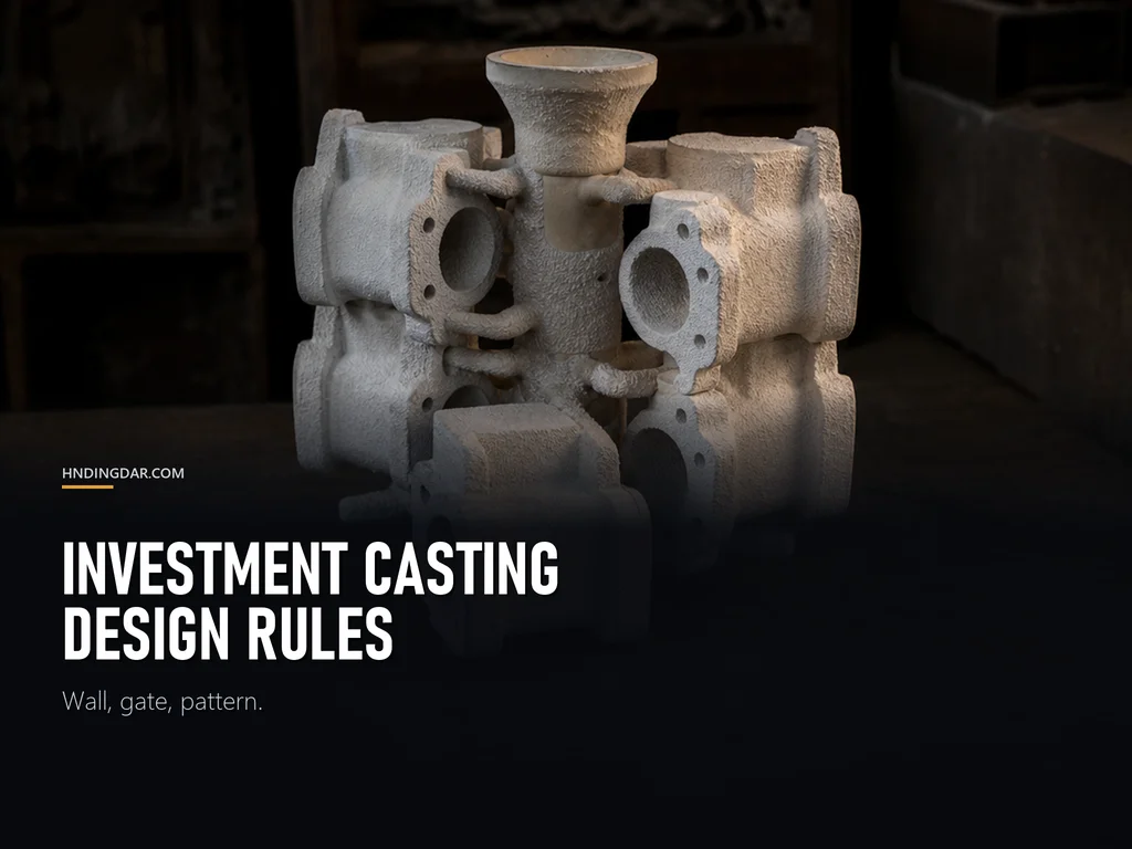
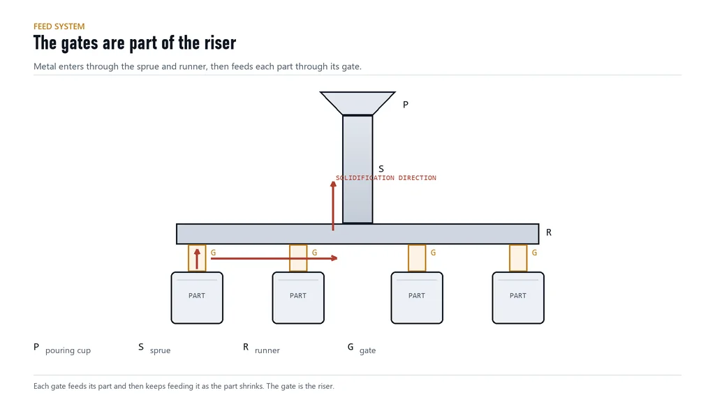
In sand casting, gating and feeding are separate. Runners bring metal in, risers feed shrinkage, and the two are designed against each other. Here they are one structure: the cluster is a single ceramic assembly, preheated and solidifying as a connected system, so the sprue and runner are the reservoir that feeds the parts.
Who decides what
The sprue carries metal down the centre of the cluster, the runner distributes it horizontally, and the gates are the short connections into each part. Their cross sections set the filling pattern: the smallest section chokes the flow and sets fill rate. Those values belong to the foundry.
Why gate position is a design decision
Because the gate is also the feeder, its position decides which end of the part solidifies last. Gate into a thin wall and the heavy section beyond it starves. Gate into the heavy section and thin extremities may not fill. The right gate usually sits on or near the heaviest mass, or on a face that will be machined anyway.
The gate also leaves a stub that is cut and ground off, so marking acceptable gate zones on the drawing saves argument later.
Turbulence and dirt
A ceramic cavity cannot vent through a permeable sand wall, so the fill must be orderly. Free fall, sharp turns and splashing fold surface oxide into the metal, and that oxide shows up as inclusion defects during machining rather than at casting inspection. Filters and generous radii at direction changes keep flow smooth.
Holes, Slots and Internal Cavities
Holes come in two kinds. One running straight through the pattern in the direction the die opens can be formed by a pin in the wax die: cheap, accurate, and small relative to its length. One that runs at an angle, curves, or sits entirely inside the part needs a ceramic core.
What a core can and cannot do
A core is placed in the wax die, wax is injected around it, and the core goes through shelling and pouring inside the pattern. It is removed afterwards by leaching or mechanical knockout. Cores make internal passages possible and cause most of what goes wrong with them.
A core must be located, and its prints either sit on a surface that will be machined away or leave a mark. Long slender cores deflect under incoming metal, which shows as a wall thick on one side. Cores break during pouring. And a core must come out: a large internal volume behind a small opening may cast perfectly and never be cleanable.
Working rules without numbers
Keep cores as straight and short as function allows, and put prints on machined faces. Avoid combining a cored cavity with a tight flatness callout on the wall around it. Open a slot on one side rather than closing it into a tunnel, and check that blast media, leach liquor and probes reach the inside; a cavity nobody can inspect is a cavity nobody can guarantee.
Slots formed by thin die walls are limited by wax strength rather than metal flow, so a slot that looks fine on the drawing can produce patterns that tear on ejection. Widening it, or cutting it in a machining operation, is often cheaper.
Distortion and Tolerance: What the Process Holds and What It Does Not
This process has a reputation for tight tolerance and, in specific respects, earns it. ISO 8062 grades castings by process, and the grade a feature can hold still depends on how that feature is formed: some attributes are held almost for free, others move in ways no drawing note fixes.
Held well: repeatability cavity to cavity, since every pattern comes from the same die, plus fine as-cast detail and the relative position of features formed in one die block. Moves: flatness over a long span, straightness of long thin parts, concentricity across two die members, and hole position through a slide. Wax creeps, the shell expands and sinters, the metal contracts, and the shell and gate stub restrain the part. Each effect is small; together they decide whether the part arrives straight.
| Attribute | How the process behaves | What closes the gap |
|---|---|---|
| Position of features in one die block | Good | Nothing, use it |
| Flatness over a long span | Moves during shell and cooling | Straightening fixture, or machine the face |
| Concentricity across two die members | Affected by die wear and mismatch | Machine one bore from a single setup |
| Hole position through a slide | Shifts with slide wear | Cast undersize and drill, or add a print |
The remedies are process remedies, not drawing notes. Straightening or coining in a fixture while the part is warm is standard for long flat parts, and a datum pad machined first is standard where a reliable reference is needed. A tolerance the shell cannot hold should move to machining deliberately, on the drawing, rather than at first article.
From Drawing to First Article: The Sequence and the Checks
A design rule is only useful if somebody verifies it. Each step below has a check that either passes or sends the job back.
DFM review. Wall uniformity, gateable mass, cored features, parting placement and tolerance allocation are checked. The output is a marked up drawing, not a price.
Die design review. Parting, slides, ejection, shrinkage allowance and print locations are agreed. This is the last cheap moment to change geometry.
Die build and wax trials. First patterns are measured and weighed. Pattern weight is a fast indicator of die fill and cavity consistency.
Pattern approval. Wax dimensions, surface, parting witness and core location are signed off. Approving a pattern is approving the geometry.
Shell and pour trial. Shell integrity, gating, fill behaviour and hot tearing are observed on the first pour.
First article inspection. Dimensional report, radiography or sectioning of critical sections, and confirmation that machining stock is where it was planned.
Correction loop. Die or gating changes are made and the affected checks repeated. A first article that needs no correction is possible, but treat it as a surprise rather than a plan.
None of this asks buyers to become foundry engineers. It asks them to arrive with questions. Ask which steps the supplier performs in house, and what happened the last time a die needed correction. The answers say more than a certificate list, and the foundry and quality organization behind our own route is described on the company page.
Where It Fits Against Sand and Lost Foam
This route is not the default. It is what you choose when geometry, wall section or surface detail cannot come from a cheaper mould.
Sand casting takes the large, heavy and simple parts: thick sections, generous draft, a parting line you can live with, and tooling that costs far less than a wax die. Looser tolerance and a greater minimum wall, but for a part measured in hundreds of kilos it is the only sensible answer.
Lost foam sits between. The foam pattern is consumed by the metal, so there is no draft and no parting line, and complex shapes need no wax die. The constraints move to foam density and coating behaviour.
This route wins where the part is small to medium, walls are thin, detail is fine, internal geometry needs cores, and volume justifies a die. It also removes machining more often. Where those conditions fail, forcing a part into a shell adds cost without value. The comparison for wear parts is set out in how to choose a casting process for wear parts, and our range is on the castings we produce page.
Conclusion
The rules reduce to four questions, none with a universal numeric answer. Can the metal fill the section and still be fed? Can the wax and shell survive the shape? Can the gating reach the mass that needs feeding, from where the stub can be removed? Can the internal geometry be cored, located and cleaned?
Answer those at the drawing stage and the part will run. Leave them for first article and you pay in die corrections and lost weeks.
Fact: DINGDAR holds ISO 9001, IATF 16949, ISO 14001 and ISO 45001, produces more than 5,400 part numbers, and answers technical enquiries within 12 to 24 hours.
If a drawing is in review, send it with the alloy, the annual volume and the features you cannot change. A DFM response should come back with the concerns marked on the geometry and a first article plan. Send the drawing for a DFM review and the team will reply.
FAQ
What is the minimum wall thickness for investment casting?
There is no single figure that applies to every part. The minimum depends on the alloy, the weight of the casting, how far the metal travels from the gate, and the inspection level required. A wall that fills easily beside the gate may not fill at the end of a long rib. Set it with the foundry for your part, then confirm it on the trial casting.
Can investment casting make internal cavities?
Yes, using ceramic cores placed in the wax pattern, which survive pouring and are removed by leaching or mechanical knockout. The limits are core location, core slenderness, and whether the cavity can be cleaned and inspected. A large internal volume behind a small opening may cast perfectly and never be cleanable.
How long does it take to get a first article?
It depends on die complexity, the number of slides and cores, and the tooling queue. The sequence is fixed even when the calendar is not: die design review, die build, wax trials, pattern approval, shell and pour trial, dimensional report, then a correction loop. Ask for that sequence in writing with dates against each step.
Can investment casting eliminate machining?
Often it reduces machining, and sometimes it removes it. As-cast detail, thin walls and small features are strong points, so a part that only needed machining for shape can often be used as cast. What remains is machining for function: sealing faces, bearing bores, threads and any tolerance tighter than the shell can hold.
Why do wax patterns distort before they reach the shell line?
Wax is a thermoplastic with modest strength. Patterns bend when warm, chip when cold, sag when unsupported, and creep in a warm room. Injection stress also relaxes in the first hours after ejection. Support fixtures, flat trays, controlled storage and a defined window between injection and treeing solve most of it.
Does investment casting need draft angle?
It needs draft in the wax die, not in the mould. The shell has no parting plane and is broken away after pouring, so nothing is drawn from it. Because die surfaces are smooth and wax shrinks as it cools, the draft required is small, but not zero, and the parting line still leaves a witness mark that must go somewhere acceptable.
Sources
- ISO. "ISO standards catalogue." https://www.iso.org/standards.html. Referenced for the published standards framework around casting tolerances and quality management.
- ASM International. "ASM Handbooks, Volume 15: Casting." https://www.asminternational.org/. Reference for solidification feeding and directional solidification as used in the gating section.
- American Foundry Society. "Metalcasting technical resources." https://www.afsinc.org/. Industry reference for casting defect classification discussed above.