Close Tolerance Castings: What Determines the Tolerance You Get
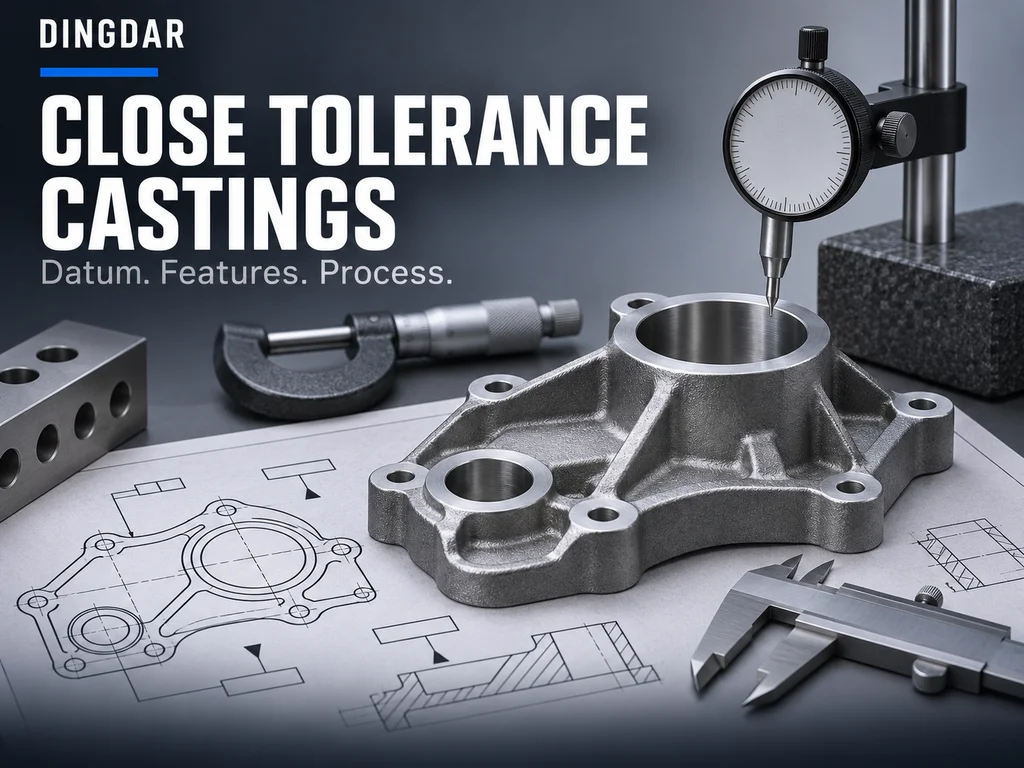
A buyer writes close tolerance castings into an RFQ and expects the phrase to carry a specification. Inside the foundry it means several things at once: the scatter of a route, the accuracy of a pattern or die, the geometry of the tolerated feature, and the machining that may follow. Compressed into two words, those layers vanish, and two suppliers can quote the same drawing while committing to different things.
This article does not publish a table of achievable tolerances, because a number copied out of context causes the dispute rather than settling it. What follows is what sets the tolerance, which features accept a tight call, how four routes shift the tendency, and how to annotate and verify the result.
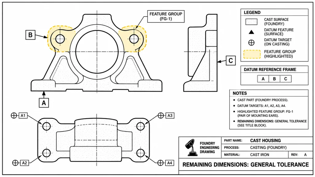
Why the phrase close tolerance castings causes disputes
The problem is not that the phrase is vague. It merges three systems that must all hold the same number, and only one belongs to the foundry.
The casting process creates as-cast surfaces. Its scatter comes from the mould, the tool, the metal and the way the part cools.
Machining creates the surfaces the tightest tolerances live on. A bore, a spigot or a gasket face reaches final size on a machine tool.
Inspection decides whether the part passes. A tolerance that cannot be measured repeatably is not a tolerance, it is an argument waiting for a shipment.
When a drawing says tight and nothing more, all three are free to read it differently. One supplier quotes as-cast and assumes the customer machines. Another quotes finished and adds a fixture nobody asked for.
The word close is also relative, because the drivers scale with the size of the part, its sections and its tooling.
The useful replacement is a sentence: these features, to this tolerance, verified this way, on this route.
Fact: DINGDAR has produced castings since 1986, now 40 years, and runs four in-house casting routes: green sand, shell moulding, lost foam and investment. Tolerance calls are reviewed by engineering against the route that will actually make the part.
Where the tolerance actually comes from
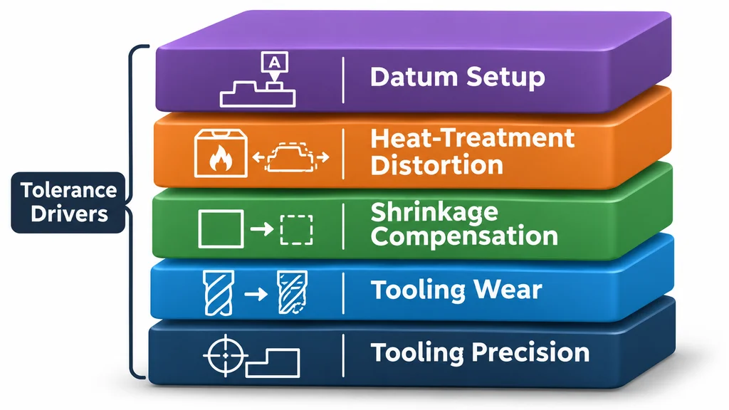
The honest answer to what tolerance a foundry can hold is a range that depends on the feature, because five physical mechanisms add up.
The tool is made to its own tolerance
Every casting begins as a cavity. The pattern, core box or die is machined and assembled to a tolerance of its own, so the casting inherits that error before any metal is poured. On a split tool the halves can sit out of register, and in a core box the print position sets where every cored feature lands. A part cannot be more accurate than the tool that defines it.
The tool changes over its life
Patterns and dies wear. Edges round, draw surfaces polish away, and the cavity drifts in one direction as cycles accumulate. The drift is a trend rather than a step, which is why a part comfortable at the first article can be marginal a year later. Multi-cavity tools make it worse, because the tolerance is met by the worst cavity.
Shrinkage compensation is a rule, not a number
Metal contracts as it freezes and cools, so the tool is built oversize by a compensation factor. That factor is not constant: it varies with section thickness, restraint, alloy and mould stiffness. One scale applied to a whole tool can be right at one feature and wrong at another, so compensation starts as a rule and is corrected after measurement.
Heat treatment moves the part
Stress relief, normalising, quenching and tempering all move metal. A casting inside its band as-cast can leave the furnace outside it, and straightening adds scatter and residual stress of its own. When a part is heat treated and tightly tolerated, the sequence carries weight: rough machine, treat, finish machine gives a different result from cast, treat, machine.
The datum decides what the number means
A tolerance is measured from something. If the datum is a cast surface with draft and texture, the measurement starts on unstable ground. If it is a machined face, someone must establish it first, in a defined order and with defined clamping, and core location, clamping force and fixture stiffness all feed the result.
Which features accept a tight call and which fight it
Within one part, the achievable tolerance varies by feature type. The pattern is consistent: a feature that is one tool surface under one setting is easier to hold than a feature that is the difference between two independent surfaces.
Centre distance versus single diameter
Centre distance between two holes produced by one core is a tool dimension, so if the tool is right the casting repeats. Hole diameter is a different question. In a sand mould the core surface is washed by flowing metal and coated with refractory, so diameter scatters more than position and carries taper. A pair of holes can land where it should while neither hole is round. Drilling reverses the balance: diameter becomes tight and position depends on the fixture.
Mating faces versus free faces
A face that bolts to something needs flatness, position and a surface a seal can grip, and those come from machining. An as-cast face can be flat enough for a bracket to rest on, but it carries draft, a parting line and a skin, and no gasket should be expected to hold on it. A face whose only job is to be there needs no tight call, and tolerancing it tightly buys accuracy that does nothing.
Thin walls versus heavy sections
A wall is the space between two surfaces. Tolerance both and the wall inherits the sum, so a thin wall is the hardest dimension on the part: two cores must sit in the right relation and core shift eats the section. Heavy sections are dimensionally calmer but harder to feed, so their problem is soundness. When the wall is the functional feature, tolerate the wall, and wall thickness and draft are covered in wall thickness and draft DFM rules.
Features at a parting line, a core print or a gate
The worst places for a tight tolerance are where two tool parts meet and where metal enters. A dimension across a parting line carries the register error of the halves. A feature on a core print carries the print clearance. A surface next to a gate carries grinding marks and a heat affected zone. None is impossible, but each asks the tolerance to buy more process control than the feature is worth.
How the four routes shift the tendency
The four routes a foundry normally offers are not a ranking. Each moves the tendency in a different direction, and the reason matters more than the order.
Green sand has the widest scatter: the mould is compacted sand whose hardness varies across a flask, the pattern is drawn from a flexible cavity, and sand expansion at the mould face moves metal. Its strength is size.
Shell moulding uses a rigid thin shell built over a heated pattern. The cavity repeats better, the surface is smoother, and stiffer cores let cored features hold position.
Lost foam removes the parting line and the draft, because the pattern is consumed. Each part gets a fresh pattern from the same mould, so wear acts on foam rather than on the cavity the metal sees. Against that, the foam is glued and coated, it can distort during filling, and glued inserts are the weak point for position.
Investment casting starts from a metal die and builds a rigid ceramic shell with no parting line, and it fills thin sections well. Its tendency is the tightest of the four for small and medium parts, with distortion arriving through shell build, wax assembly and the firing cycle. The investment casting process page covers what that means for design detail.
| Route | As-cast tendency | Physical reason | Where a tight call is realistic |
|---|---|---|---|
| Green sand | Widest scatter | Compacted mould, pattern draw, expansion | Large parts, where size matters |
| Shell moulding | Moderate | Rigid shell, stiffer cores | Medium cored parts |
| Lost foam | Moderate, weaker at joints | Glued assembly and coating | No-draft, seamless parts |
| Investment | Tightest repeatability | Metal die, rigid shell | Small features, thin walls |
Read the table as direction, not as a promise. The route sets the starting scatter, and tooling quality, feature design and process control decide where inside that range a part lands. A controlled sand line can beat a neglected investment shop on one feature, and no route removes the need to verify. A line configured around a part family keeps those settings stable, which is what a custom foundry line is for.
Annotating the drawing so it cannot be misread
Most tolerance disputes are drawing problems before they are production problems. A drawing two shops can read differently will be read differently.
Fix the datum system first
Choose datums that exist: three planes, or a plane and two holes, in a sequence a fixture can reproduce. On a casting the primary datum is often a machined face established in the first operation, and the drawing should say so. Cast surfaces used as datums need target points, because a full face with draft is not a reliable plane.
Separate the few critical dimensions from the rest
A drawing where everything is tight has no priorities, and the shop ends up treating a cosmetic rib like a bearing bore. Mark the handful of dimensions that carry function with individual tolerances and leave the rest under a general note. This is where a general tolerance grade earns its place: it assigns a band by feature and size range, so the drawing states a level of control once.
ISO 8062-3 is the framework most casting drawings lean on, and it treats general dimensional tolerance, general geometric tolerance and machining allowance as separate grades. Choose the grade for the features that stay as-cast. Applying it to the whole part, including surfaces that will be machined, describes a casting nobody needs to make.
Size against geometry
A size tolerance on a hole does not control where the hole is, and a size tolerance on a face does not control flatness. When function is fit, position or sealing, the control has to be geometric and referenced to a datum. Position and profile matter most on castings and are the most often left off.
Three things to settle before capability is discussed
By the time a tolerance is agreed, three commitments sit behind it. None is a tolerance value, and all three decide whether the value survives production.
Evidence of capability
Ask for the first article report and read which features it covers. A report with three dimensions and a general note is not evidence for a tightly tolerated feature set. What you want is a dimensional report per cavity on the tight features, with the method stated. A short study on the variable data then shows whether the process is centred or merely inside the limit on the day it was measured.
The pattern borrowed from production part approval works outside automotive supply too: a control plan naming the feature, the gauge, the frequency and the reaction when a result drifts. A supplier that can show the plan can hold a tolerance over a year, not just over a first article.
One measurement method, agreed
The same casting can pass on a coordinate measuring machine and fail on a caliper, and both results can be honest. Instrument, datum setup, clamping, temperature and operator all move the number. Agree the method on the drawing: which instrument, which datum sequence, whether the part is measured free or restrained, and who owns the gauge and its calibration.
Free state matters more than most buyers expect. A thin casting clamped in a fixture measures to the fixture and springs when released. If the drawing does not say which condition applies, the argument is settled by whoever inspects last.
A disposal path for out-of-tolerance parts
Decide before the first shipment what happens when a feature misses. The options are rework, concession with an engineering evaluation, sort and replace, or scrap, and each needs an owner and a data pack. A concession request with a measurement report, a map of the deviation and an assessment of function is a decision. The same request with a photograph and an apology is a delay.
Two distinctions keep this practical. A trend is not a one-off: one part outside the band is a containment question, a rising share is a process question. And traceability by cavity and by heat is what makes a sort possible without inspecting everything twice.
Fact: DINGDAR operates 180,000 m2 of production plant with 720+ employees, including 52 engineers and R&D staff, and holds ISO 9001, IATF 16949, ISO 14001 and ISO 45001 certification. Four casting routes in one plant is what allows a tolerance to be answered against a specific route instead of an average.
Where machining takes over from casting precision
At some point the rational answer is to stop asking the mould for accuracy. The test is not how tight the tolerance is, but where it sits.
Position between two machined features comes almost free, because one setup establishes both. Position between a machined feature and an as-cast feature carries casting scatter plus fixturing error, and no amount of machining removes the second half. A surface that must seal or locate a bearing gets machined, and a feature that cannot be fixtured has to be carried by the casting.
When the answer is machining, the casting is ordered with stock and the drawing says so. How much stock to leave is a separate decision, worked through in machining allowance for castings. What belongs here is the boundary.
Machining is the better route when the band is narrower than the process scatter, the feature is a fit or a seal, and the geometry gives a stable setup. Raising casting precision is the better route when the feature is internal or too large to fixture, when the surface carries a wear or sealing function that must not be cut away, or when the part is thin enough that clamping distorts it.
The trap is treating the decision as global. Adding stock everywhere to rescue three features creates heavy sections that feed badly, opens porosity under the cut and adds passes on faces that were already fine. Decide per feature and write it per feature.
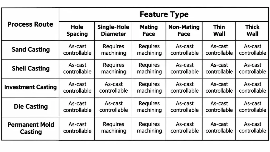
Feature by feature: controllability and verification
Use the table to classify a drawing before the RFQ goes out. Read the middle column as how much of the tolerance the casting process can own, not as a value, and note that the last column is where most disagreements start.
| Feature type | As-cast controllability | Main drivers | How to verify |
|---|---|---|---|
| Hole position within one core | High | Core box accuracy, core location | CMM or functional gauge |
| Cored hole diameter | Low to moderate | Core wash, coating, taper | Bore gauge or CMM at depth |
| Machined bore diameter | High, after machining | Machine tool, tool wear, fixturing | Bore gauge, air gauge, CMM |
| Mating face after machining | High | Setup, datum sequence, clamping | Flatness on a plate, profile scan |
| As-cast mating face, unmachined | Low | Draft, distortion, parting line | Surface plate against targets |
| Wall between two cores | Low | Core shift and mismatch | Ultrasonic thickness, section cut |
| Rib or web thickness | Moderate | Fill, coating, pattern draw | Caliper at defined stations |
| Length between two as-cast faces | Moderate | Tool size, shrinkage compensation | CMM on datum targets |
| Slot formed by one core | Moderate to high | Core strength, wash, support | CMM position, go and no-go gauge |
| Thread | Not as-cast | Requires machining after casting | Thread gauge after machining |
Two rows deserve attention because they are where drawings go wrong: the as-cast mating face and the wall between two cores. Both look like ordinary dimensions on paper, and both ask the process to do something it cannot. Either machine the face or move the fit onto a machined feature, and either tolerate the wall deliberately or thicken it.
Where the tolerance call ends
A tolerance is not a property of a casting, it is an agreement about a feature, measured one way, on one route. The buyer who understands that stops asking for close tolerance castings in general and starts naming the features that matter.
For a second opinion on a tolerance stack before a pattern or die is cut, the engineering team reviews the drawing against the route that will make the part. Start with about us for the plant and the four in-house casting lines, then send the drawing through contact. Replies usually come back within 12 to 24 hours.
FAQ
What tolerance can close tolerance castings actually hold?
No single figure exists, and any page that gives you one has not asked about the part. The answer depends on the route, the feature type, the part size, the tooling condition and the measurement method, so ask for it per feature group and in writing.
Do close tolerance castings need 100 per cent inspection?
Usually not. Full inspection is a containment action, not a process. Start with a first article per cavity on the tight features, then sample at a frequency set by how close the process runs to the limit. Move to full inspection only while a deviation is being contained.
Who supplies the gauge, and who owns the measurement result?
Whoever signs the inspection report owns the result, but the gauge has to be agreed first. Either the foundry measures on a calibrated instrument, or the buyer measures and the foundry accepts the method. Two gauges with no written agreement let both parties be correct and still disagree.
What happens if the parts arrive out of tolerance?
It depends on what was agreed before shipment. Fix the path in advance: rework, concession with an engineering evaluation, sort and replace, or scrap. A concession request needs a measurement report, the location of the deviation and a view of function, not a photograph.
Can a cored hole be held as tight as a drilled hole?
Rarely on diameter, often on position. A cored hole in a sand mould is shaped by a core the metal erodes and coats, so its diameter scatters and it carries taper. Two holes from one core hold centre distance well. If the fit is on the diameter, plan to machine it.
Which casting route should be chosen for the tightest features?
The one whose scatter is smallest for that feature type, which usually points to investment casting for small parts and thin walls, and to shell moulding for medium parts with cored features. Tooling condition and feature design move the result more than the route label.
Sources
- ISO 8062-3:2023, Geometrical product specifications (GPS), dimensional and geometrical tolerances for moulded parts, part 3: general dimensional and geometrical tolerances and machining allowances for castings. https://www.iso.org/standard/77952.html
- American Foundry Society, technical and educational resources on metalcasting practice. https://www.afsinc.org/