Machining Allowance for Castings: How Much to Leave and Where
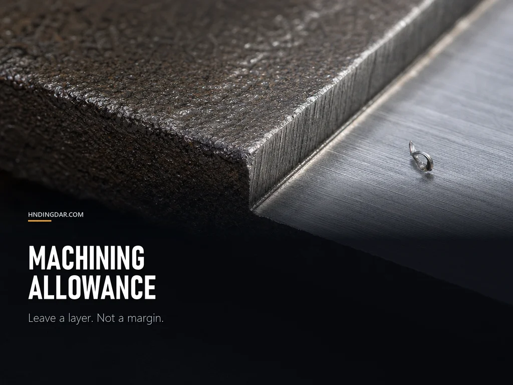
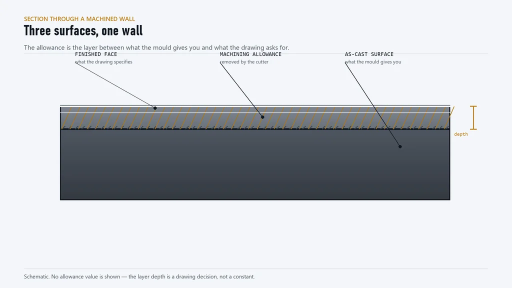
A machining allowance is the layer of metal left on a casting for a machine shop to remove. It is often the least discussed line on a casting drawing and one of the most disruptive to get wrong, because by the time the error appears the pattern is cut and the batch poured.
Search for guidance and the same table appears on a dozen sites: an allowance for cast iron, one for steel, one for aluminium, indexed by part length. The table is not fiction, but it is not usable alone, because it says nothing about which faces carry stock.
This guide works the other way round, from the face, the process and the datum to the number. No universal value appears here, because none exists. The allowance for a part is set by the supplier against its process, alloy and geometry, then confirmed on the first article.
An allowance is a process buffer, not a safety margin
The instinct behind extra stock is easy to defend. If the casting comes out low, the machine shop can still cut to the final dimension. Stock looks like insurance.
The insurance is not free, and the penalty shows up in three places a quotation rarely shows.
Machining time and tool condition
Cast surfaces are not clean metal. They carry moulding sand, oxide scale, a chilled skin, and on some alloys a decarburised layer, all harder or more abrasive than the section underneath. Cutting through a heavy layer at roughing depth is where inserts chip.
A thermal node under the machined face
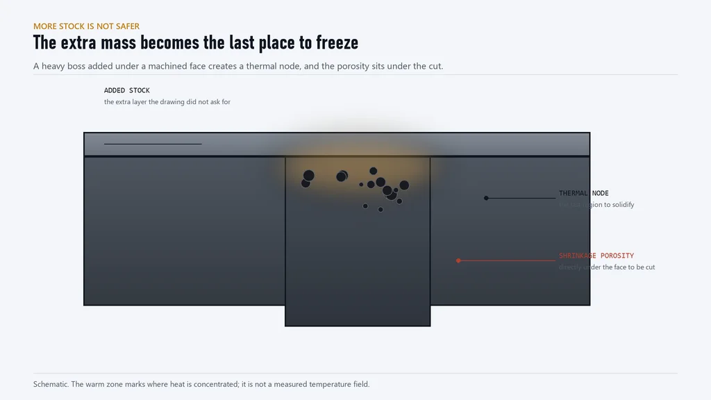
Metal added to a face is metal added to a section. When the mass sits at a junction, an inside corner or a boss root, that region solidifies last and without a feed path. Shrinkage porosity forms exactly under the surface about to be cut. The tool opens it, and the defect reaches inspection looking like a machining fault when it was designed in.
A harder part to inspect
Radiography and ultrasonic testing rely on a sound path through the section. An abrupt change of thickness scatters the signal, and stock machined away later removes the material an inspector would have examined.
Fact: DINGDAR has produced castings since 1986 and runs four in-house casting routes: green sand, shell moulding, lost foam and investment. Allowance, datum and machined-face definition are reviewed by engineering before a pattern or die is cut, which is the last point where the decision is still cheap to change.
The rule is short. The allowance should absorb the variation the process cannot avoid, and nothing more. Everything beyond that creates the defects it was supposed to prevent.
Which faces need an allowance and which do not
The allowance is a per-face decision. Treating it as one global offset is the most common mistake on a casting drawing, and why shops chase cleanup along a face.
Faces that normally need stock
Mating and fit faces. Bolted joint faces, spigots, register diameters, dovetail slides. Their function is position and flatness, and both come from machining.
Sealing faces. Gasket lands, O-ring grooves and flange faces. A cast surface cannot hold a seal, because roughness, a cold lap or surface porosity will leak under pressure. Pump and valve casting inspection shows how those faces are checked after machining.
Bearing seats and bores. Press fits, bushing bores and shaft journals need roundness, straightness and a fit tolerance the casting process does not deliver on its own.
Threaded holes and spot faces. A tap needs clean metal through the thread length. Cast skin at the bottom of a cored hole, or a core that floated, puts inclusions where the thread roots will be.
Faces that usually should not
Cosmetic and exposed surfaces. As-cast texture is often the finish the customer wants, and machining removes the skin that hides minor mould marks.
Ribs, webs and thin bosses. These are section-critical. Stock on a rib is stock taken out of the strength calculation, and machining a thin rib shows how much the fixture deflects it.
Fillets and radii. There is no sensible way to machine a fillet without changing the stress flow it exists to smooth.
Drafted walls. A drafted wall is not parallel to the machining axis, so machining it means an interrupted cut and a finished wall that no longer matches the draft. How much draft a wall carries is set out in wall thickness and draft DFM rules. The point here is narrower: a drafted face is a poor candidate for stock.
Chilled or hardened as-cast surfaces. On wear parts the hard layer at the mould face is the wear surface. Machining it away removes the property the part was bought for.
Cored walls with stock on both sides. Stock on both faces eats a cored wall from two directions. One machined face is usually enough.
Allowance belongs on faces whose job is dimensional, not on faces whose job is shape, texture or section.
What actually decides the amount
No single factor sets the allowance. The supplier balances five or six at once, differently for every drawing.
Process scatter at the surface
Every route produces a band of variation around nominal: mould wall movement under pouring pressure, sand expansion at the mould face, pattern wear, core float, coating thickness, foam density, shell thickness. The allowance on a face has to exceed that band, in the direction that matters, or cleanup is not guaranteed.
Distortion during solidification and cooling
Long, thin parts bow. Flat plates dish. U-sections open at the top. Distortion is not uniform, so the stock needed to machine a face flat varies along that face. This is where a single number quietly fails: right at the middle, short at the corner.
Heat treatment
Stress relief, normalising and quenching all move the part. If machining follows heat treatment, the allowance covers that movement. If a part is roughed before treatment and finished after, the roughing stock covers both the casting scatter and the treatment movement.
Fixturing and datum choice
A part located on a rough cast face inherits the scatter of that face in every machined feature. A part located on a machined datum is stable, and the datum face needs stock to be machined first. Fixturing and allowance are one decision seen from two sides.
Size, stiffness and alloy
The same process holds a small bracket far tighter than a long bed, because errors accumulate over distance and the part deflects under its own clamping. Fluidity, shrinkage and hot tearing resistance then decide how much the casting moves and how much feed metal the section needs.
Fact: DINGDAR operates 180,000 m2 of production plant with 720+ employees, including 52 engineers and R&D staff, and holds ISO 9001, IATF 16949, ISO 14001 and ISO 45001 certification. Four casting routes in one plant is why allowance advice can be process-specific instead of averaged.
The result is written as a machining allowance grade, in the sense used by ISO 8062-3, or as a per-face note on the casting drawing. Either way it belongs to the supplier's process.
How the casting route shifts the tendency
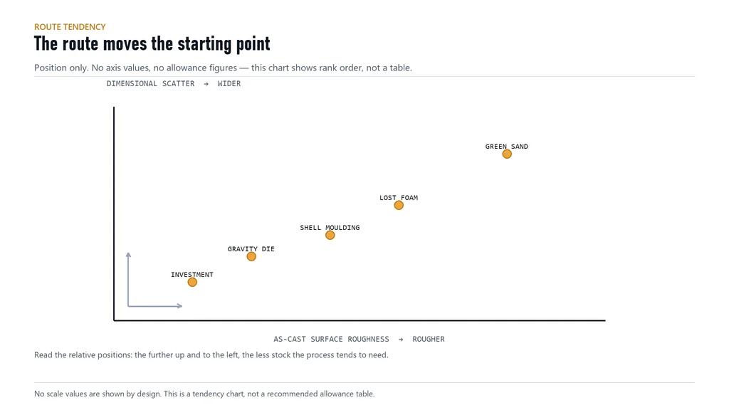
The route changes the surface and the dimensional scatter, so it changes the tendency of the allowance. Tendency only: the value still comes from the part.
| Route | As-cast surface | Dimensional scatter | Allowance tendency | Main driver |
|---|---|---|---|---|
| Green sand | Rough, sand texture, parting line mismatch | Widest of the sand routes | Highest | Mould wall movement, ramming, sand expansion |
| Shell moulding | Smoother, stiffer mould | Narrower than green sand | Moderate | Pattern quality, shell thickness uniformity |
| Lost foam | No parting line, no draft, smooth | Moderate but pattern-driven | Moderate and uneven | Foam shrink, cluster assembly, coating |
| Investment | Finest surface, fine detail | Narrowest | Leanest | Wax tooling, shell build, firing |
| Gravity casting (permanent mould) | Smooth, fine grain at the die face | Narrow and repeatable | Lean, but die-bound | Die temperature, die wear, ejection |
Green sand is the workhorse route for large, complex moulds and the roughest at the surface. Mould wall movement and ramming variation are real, the parting line can mismatch, and the allowance tends to sit high on large flat faces.
Shell moulding stiffens the mould with a resin-bonded shell. Surface and repeatability improve, so the tendency drops, but pattern quality and shell uniformity now carry the variation.
Lost foam removes the parting line and the draft requirement, which changes the failure mode more than the number. The pattern is a foam assembly, so foam shrinkage, glue joints and cluster rigidity drive the scatter, and a machined face still needs stock to cover pattern-driven variation rather than mould wall movement. Lost foam casting is worth reading alongside this section for one-piece hollow shapes.
Investment casting gives the tightest surface and dimensional control, so the tendency is leanest. Shell distortion during firing and wax tooling condition are the remaining drivers, and thin sections are limited by fill rather than stock.
Gravity casting in a permanent mould is a different family. The metal die holds dimensions and repeats them, so the tendency is lean and stable, but the die face chills the casting, die wear accumulates, and ejection adds a constraint. Gravity casting explains why the first parts off a new die are treated as a separate question.
The ranking is not absolute. A 300 kg green sand part and a 2 kg investment part are not comparable, and a geometry that distorts in one route can be stable in another. Read the table as a question about which way the design should lean, not as an answer.
Tie the allowance to a machining datum
An allowance that is not tied to a datum is not a specification. It is a hope.
Consider a housing with two parallel walls, one mounting to a frame and one carrying a bearing. If the casting drawing says only that machined faces get stock, the machinist can locate on either rough wall, the datum floats with the casting scatter, and every machined feature inherits it. When stock is short on one side, the operator skims until the face cleans up and the finished position shifts.
The drawing should answer three questions before machining starts:
- Where is zero? Datum features and targets marked on the casting drawing, not only on the part drawing.
- Which faces are machined, and in what order? The primary datum face is machined first, so it needs stock. Everything located from it inherits that face's accuracy.
- How much stock on each face? Per face, or by a note that references a grade for machined faces and states as cast for the rest.
Two rules save arguments later. Casting dimensions are pre-machining dimensions: the finished dimension and its tolerance are the target, and the allowance is consumed on the way there, sitting on top of the tolerance chain rather than inside it. An as-cast face used as a datum is a contradiction unless the process can hold it, which is exactly when a supplier should ask for a machined datum instead. In permanent mould work the choice is easier, because a part from a gravity casting die has one very accurate face, the die face, to locate on.
What goes wrong when the allowance is wrong
Too little stock
Black skin after machining. Patches of as-cast surface survive the cut: dark, hard, usually at a corner, a parting line or the point of maximum distortion. The face can be dimensionally in tolerance and still be scrap.
Undersized bores and thread breakout. A bore that cleans up on one side and not the other cannot be saved by boring deeper. Welding up a sealing face is often prohibited, and reasonably so.
Too much stock
Porosity opened by the cut. The thermal node now sits under the finished surface, and the last pass exposes it. On a hydraulic casting this shows up as a leak at test, long after the casting was accepted.
Wall thickness below the minimum after machining. A cored wall with stock on both sides loses section twice. Strength and heat treatment response change, and the part can pass a dimensional check while failing the job it was designed for.
A dimension chain that no longer closes. Extra passes to clean up a heavy face change the relation between features, so each dimension can sit inside its tolerance and the stack still fail at assembly.
Clamping spring and flatness loss. Uneven stock means uneven clamping force. The part measures flat under the clamps and rocks on the surface plate afterwards.
Both at once
The common real failure is uneven stock across one face: one end cleans up early and the other never does. The operator skims until the worst point is clean, over-machines the good end, and moves every feature referenced from that face.
Working with the supplier on the number
The allowance is a shared decision with a clear division of labour. The buyer owns the function, the supplier owns the process capability, and neither can set it alone.
Send two drawings, not one. The part drawing carries final dimensions, tolerances and datums. The casting drawing carries pre-machining dimensions, per-face stock, as-cast tolerances and datum targets.
Ask the supplier to propose, then review the reasoning. The useful question is not how much, but what it covers: process scatter, distortion, heat treatment movement, fixturing. If the answer is a table lookup, ask which row and why.
Name the critical faces. Sealing faces, bearing bores and mating faces are not equal. Say which cannot be reworked, so their stock is set by their risk rather than the part average.
Agree the heat treatment sequence early. Rough machine, heat treat, finish machine is a different allowance from cast, heat treat, machine, and changing it later reopens the question.
Control the casting drawing as a document. When a pattern is repaired or replaced, the assumption changes with it. A revision block is worth more than a note in an email thread.
Verify on the first article with a stock map. Measure the raw casting before machining and record actual stock at each machined face. Then check black skin, wall thickness at the thinnest cored section, and feature position from the datum. On pressure-tight parts, inspect volumetrically after rough machining, while the material under the finished surface is still there.
Check capability per cavity. The allowance that works for one cavity can be short in another, so the first article report should name the cavity.
Done that way, the allowance becomes a documented assumption that can be tested, rather than a number copied from a textbook.
Decision table: face type, allowance and risk
| Face type | Leave stock? | Main risk if wrong |
|---|---|---|
| Mating or fit face | Yes | Black skin at a corner; position shift in the stack |
| Gasket or O-ring sealing face | Yes, treat as critical | Surface porosity opened by the cut; leak at test |
| Bearing bore or journal seat | Yes | Bore out of round or undersized, with no recovery |
| Threaded hole and spot face | Yes | Thread roots in cast skin or core-shifted metal |
| Machining datum face | Yes, machined first | Datum floats with casting scatter; whole feature set shifts |
| Wear face to be ground or hardfaced | Yes | Dirty metal under the coating; spalling in service |
| Chilled or hardened as-cast skin | No | The wear property is machined away |
| Rib, web or thin boss | No | Section loss; deflection under load |
| Fillet or radius | No | Stress flow changed; no clean way to cut it |
| Cored wall | One side only | Wall below minimum thickness; leak path |
Where this leaves the drawing
None of this is exotic. It is a matter of deciding, face by face, whether the casting or the machine shop creates the final surface, and writing that decision where the shop can read it. The allowance is a process statement, not a universal constant.
For a second opinion on a casting drawing before the pattern is cut, the engineering team at DINGDAR reviews allowance, datum and machined-face definition against the actual route. Start with about us for the plant and the four in-house casting lines, then send the drawing through contact. Replies usually come back within 12 to 24 hours.
FAQ
How much machining allowance should I leave on a casting?
There is no single figure, and any page that gives you one without asking about the process, the alloy and the part is guessing. The amount is set by the scatter of the casting route, the distortion the geometry produces, the heat treatment sequence, the fixturing and the datum scheme. Ask the foundry to propose a value per machined face and say what it covers.
Can a casting be made with no machining allowance?
Yes, and many are. If a face is cosmetic, or its function is shape rather than fit, as-cast is the correct specification. The limit is the process: as-cast tolerances are wider than machining tolerances, and cast surfaces carry texture. A face that must seal, locate a bearing or hold a thread needs stock. A face that only has to be there usually does not.
Is the machining allowance charged to the buyer or the supplier?
It sits in the casting weight and in the machining hours, so someone pays either way. The split depends on what you buy. For a finish-machined part, the foundry carries the allowance inside its scope. For as-cast supply, the allowance lands in your machining time and scrap rate. Settle the number before the pattern is cut, because a change afterwards is more disruptive than the stock itself.
What happens if the casting distorts more than expected?
Distortion moves as a trend, not a step: pattern wear, a change of sand or coating, a heat treatment load that ran differently. Compare the current stock map against the first article to see which faces lost material. Short term, adjust the datum or the machining sequence. Long term, correct the pattern or the process. Adding stock everywhere recreates the thermal node problem on faces that were fine.
How do you verify the allowance on a first article?
Measure the raw casting first: actual stock at each machined face, wall thickness at the thinnest cored section, and the position of cast features against the datum. Then machine, and check for black skin, remaining wall thickness and feature position. For pressure-tight or heavily sectioned parts, add volumetric inspection after rough machining.
Why do machined castings sometimes show dark patches?
Those patches are as-cast skin that survived the cut, usually where the casting was low, where the face distorted, or where a parting line sat proud. The face can be within its dimension while carrying an unbroken cast surface, which is why black skin is a separate inspection item. The cause is almost always uneven stock, and the cure is a per-face allowance.
Sources
- ISO 8062-3:2023, Geometrical product specifications (GPS), dimensional and geometrical tolerances for moulded parts, part 3: general dimensional and geometrical tolerances and machining allowances for castings. https://www.iso.org/standard/77952.html
- American Foundry Society, technical and educational resources on metalcasting practice. https://www.afsinc.org/